7-28 SHB 28Z3 EN – Edition 2.0 * 28z3s710.fm
Options
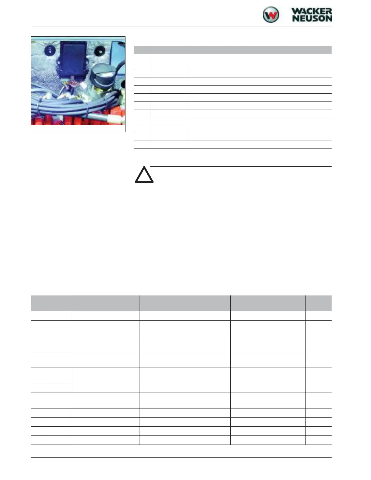
X11 supply outputs
Measures to be taken in case of malfunctions
Caution!
System breakdowns can never be excluded, therefore:
• Disconnect the electronic controls from the power supply before carrying out repair
work or maintenance on the hydraulic system.
• Stay clear of areas and parts with danger of crushing.
• Stay clear of areas between moving hydraulic components and fixed obstacles!
DANGER OF CRUSHING!
• The operator of the machine or hydraulic system must be aware of possible machine or
system errors
Diagnosis display
The control valve status is displayed to the user by means of a flashing code. The follow-
ing errors are identified by the number of flash pulses:
Fig. 20: Control unit position
PIN Designation Connections
1M_ECU Earth
2 MVH1 + channel 1
3 MVH2 + channel 2
4 MVL1A Pulse modulation channel 1/magnet 1
5 LSW2 Indicator light
6 LSW3 Indicator light
7 MVL2A Pulse modulation channel 2/magnet 1
8 MVL2B Pulse modulation channel 2/magnet 2
9 MVL1B Pulse modulation M channel 1/magnet 2
10 MOT2 Engine
11 MOT1 Engine
12 U_ECU +12 V supply
No. Pin no. Designation Error Troubleshooting
Critical
error
0 - - No error - -
1 B 5 Channel 1 input (left) Defective input voltage
Check voltage,
home position: 2.5 V
deflected: 0.7 V – 4.3 V
-
2 A4, A9 Channel 1 output; Y16/Y17 Overload or overheating (output stage) Check magnet on valve -
3 A4, A9 Channel 1 output; Y16/Y17
Short circuit on earth or operating volt-
age
Check wiring x
4 B4 Channel 2 input (right) Defective input voltage
Check voltage, home position:
2.5 V deflected: 0.7 V – 4.3 V
-
5 A7, A8 Channel 2 output; Y18/Y19 Overload or overheating (output stage) Check magnet on valve -
6 A7, A8 Channel 2 output; Y18/Y19
Short circuit on earth or operating volt-
age
Check wiring x
7 - System start - x
8 A10, A11 Motor output Overheating (output stage) Check motor x
9 - - EEProm data error - x
10 B6 +5 V joystick Defective 5 V supply - x

 Loading...