Serie 750, 753Planning
28 System manual | Version: 3.0.2
4Planning
4.1 Node Structure
Note that product-specific configuration or test steps may be necessary. For example be-
fore:
• Commissioning
• Recommissioning
• Exchange and replacement of I/O modules
These configuration or test steps are described in the respective & Product Manual.
Types of Components
Several different types of components are used in the I/O system:
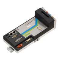
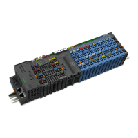
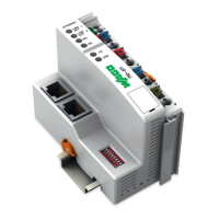
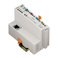
• Head Stations:
– PFC
– Controller
– Fieldbus couplers
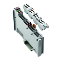
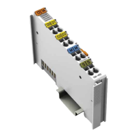
• I/O Modules:
– Analog input and output modules
– Digital input and output modules
– Function and technology modules
– Communication modules
– Supply and segment modules
Number of I/O Modules
The maximum number of I/O modules that can be operated in one node depends on sev-
eral factors:
• Mechanical Expansion:
The distance between a head station and an end module must not exceed 768mm, in-
cluding the end module. If a node is wider, it must be divided into several sections with
an additional fieldbus coupler, controller or internal data bus extension.
• Addressability:
Depending on the head station used, a maximum of 250 I/O modules can be ad-
dressed.
I/O modules that do not have any process or diagnostic data (e.g., distance modules)
do not need to be taken into account when calculating the number.
• Head Station Memory:
Head stations have a limited memory for the process image.
• Fieldbus Technology Characteristics
4.2 Structure Guidelines
4.2.1 Installation Site and Touch-Proof Protection
The WAGO I/O-System is an open system. As such, it must only be installed within ap-
propriate housings, cabinets or electrical operation rooms that fulfill at least the following
requirements:
 Loading...
