Serie 750, 753Planning
40 System manual | Version: 3.0.2
• e!COCKPIT
e!COCKPIT is an integrated development environment that supports every automation
task, from hardware configuration and programming, to simulation and visualization, to
commissioning – an all-in-one software package.
• WAGO Smart Designer Product Configurator
The Smart Designer product configurator enables true 3D configuration of WAGO’s
electrical interconnect and automation components, including the WAGO-I/O-SYSTEM
750, circuit boards and terminal blocks. With this tool you can, among other things,
configure a node of the I/O system and calculate the approximate power requirement.
• WAGO-I/O-CHECK
Application for operating and displaying a node from the WAGO 750 I/O-SYSTEM
Coding
Multi-part I/O modules from the WAGO I/O-System can be equipped with coding keys to
prevent mismatching when connecting the individual module parts.
For additional information see: 8Assembling/Disassembling Components [}48].
System Supply Power Requirement: Example Calculation
The example calculation is based on the following node structure:
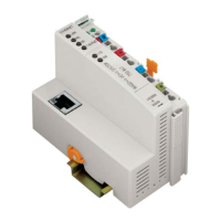
• Head station
• 5 × 16-channel digital input module
• 5 × 16-channel digital output module
• 11 × 8-channel analog input module
• 10 × 8-channel analog output module
• 2 × relay module
• I/O module ...
Table10: Power Requirement: Example Calculation
Head station 1,700 mA
5 × 16-channel digital input module (25mA) − 125mA
5 × 16-channel digital output module (40mA) − 200mA
11 ×8-channel analog input module (69mA) − 759mA
10 × 8-channel analog output module (61mA) − 610mA
Remaining total system supply current
At this point, an additional supply module must be used!
6 mA
Supply module 2,000mA
2 × relay module (100mA) − 200mA
I/O module ... − ...
Field Supply Power Requirement: Example Calculation
The field supply layout must be handled in the same way as the system supply. Addi-
tional supply modules may be needed. Detailed product information is available in the re-
spective & Product Manual.
Determining Power Loss
Power loss depends on the node structure and the applied field signals. To roughly deter-
mine power loss, use:
• Head station: 3W
 Loading...
