Serie 750, 753 Planning
System manual | Version: 3.0.2 31
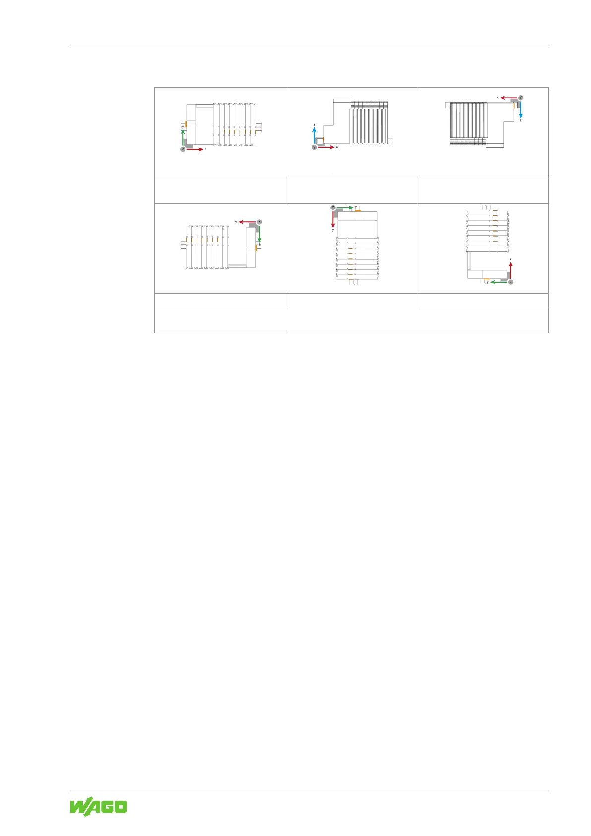
Overview of Mounting Positions
Nominal mounting position (horizon-
tal left)
Floor mounting position Ceiling mounting position
Mounting position, horizontal right Mounting position, vertical top Mounting position, vertical bottom
For vertical installation, always mount an end stop below the node to pre-
vent it from slipping off.
4.2.6 DIN-Rail Characteristics
To ensure optimum system construction, all system components can be securely
snapped onto a DIN-rail (35mm). Observe:
• The material must have high corrosion resistance.
• The DIN-rail geometry must not be altered.
• Prevent bending and twisting (torsion) e.g., by using sufficient attachment points.
• Use countersink-head screws, blind rivets, etc., to countersink the attachment points
beneath the node structure.
• The component DIN-rail contact (CuSn6) must not form a galvanic element with the
DIN-rail that is capable of generating a differential voltage of more than 0.5V (saline
solution of 0.3% at 20°C/68°F).
4.2.7 EMC Installations
• Ground the DIN-rail
Ground the DIN-rail to divert electromagnetic interference.
• Use shielded cables for data and signal lines
Use of shielded cables reduces electromagnetic interference and increases signal
quality. Measurement errors, data transmission faults and interference due to exces-
sive voltage can be prevented!
• Keep data and signal lines separate from interference sources
Route data and signal lines separately from all power supply cables and other sources
of high electromagnetic emissions (e.g., frequency converters or drives).
• Connect the cable shielding with the ground potential
Integrated shielding is mandatory to meet technical specifications regarding measure-
ment accuracy. Connect the cable shielding and ground potential at the inlet to the
cabinet or housing. This grounding allows induced interferences to dissipate and be
kept away from devices in the cabinet or housing.

 Loading...


