Serie 750, 753 Assembly and Disassembly
System manual | Version: 3.0.2 43
6Assembly and Disassembly
DANGER
Do not work on products while energized!
High voltage can cause electric shock or burns!
• Disconnect all power sources from the product before performing any installation, re-
pair or maintenance.
Note
Note planning documents!
The structure of the node and installation in the system may only be carried out in accor-
dance with the planning documents provided by the system planner.
The following information must be provided:
• Information about the correct node structure
• Information about permissible mechanical, electrical and climatic ambient conditions
• Circuit diagrams
• Mounting position, cable types and lengths
6.1 Assembly Sequence
The components of the I/O system must be snapped directly onto a DIN-rail. Starting with
the head station, the I/O modules must be installed from left to right according to the
project design, in the nominal mounting position.
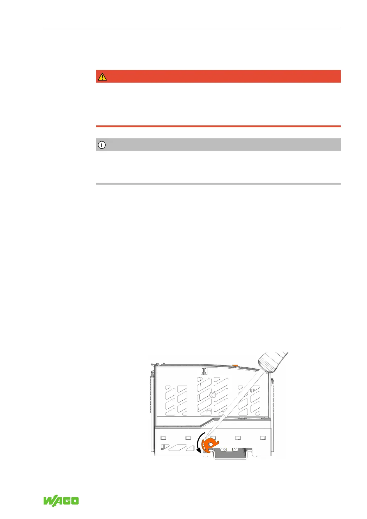
6.2 Snapping the Head Station to the DIN-Rail
1. Snap the head station onto the DIN-rail.
2. To attach the head station to the DIN-rail, use an operating tool to turn the DIN-rail
locking cam until the nose of the DIN-rail locking cam engages behind the DIN-rail.
Figure21: Locking the Head Station

 Loading...


