EasyManuals Logo

WAGO 750 Series System Manual

WAGO 750 Series
56 pages
To Next Page IconTo Next Page
To Previous Page IconTo Previous Page
Page #44 background imageLoading...
Page #44 background image
Serie 750, 753Assembly and Disassembly
44 System manual | Version: 3.0.2
ð The head station is now locked on the DIN-rail.
6.3 Attaching an I/O Module
1. Position the I/O module in such a way that the grove and spring are connected to the
preceding and following components.
Figure22: Inserting the I/O Module
2. Press the I/O module into the assembly until the I/O module snaps into the DIN-rail.
Figure23: Snapping in the I/O Module
3. Check that the I/O module is seated securely on the mounting rail and in the assem-
bly.
ð Once the I/O module has snapped into place, the electrical connections for the data
contacts and power contacts (if any) to the head station or to the preceding and, if ap-
plicable, following I/O module are established.

Table of Contents

Other manuals for WAGO 750 Series

Questions and Answers:

Question and Answer IconNeed help?

Do you have a question about the WAGO 750 Series and is the answer not in the manual?

WAGO 750 Series Specifications

General IconGeneral
Protection ClassIP20
Bus CouplersPROFIBUS, CANopen, Ethernet
ModulesDigital Input, Digital Output, Analog Input, Analog Output
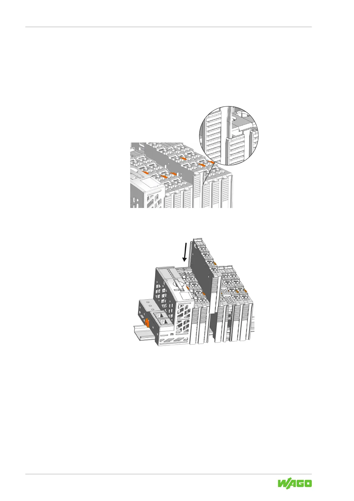
MountingDIN rail mounting
Voltage Supply24 V DC (typical)
Communication ProtocolDepends on the bus coupler (e.g., PROFIBUS, CANopen, DeviceNet, Ethernet)
Digital Input ChannelsVaries by module (e.g., 8, 16 channels)
Digital Output ChannelsVaries by module (e.g., 8, 16 channels)
Analog Input ChannelsVaries by module (e.g., 2, 4, 8 channels)
Analog Output Channels1, 2, 4 channels (depending on module)
Width12 mm, 24 mm (typical module widths)
Number of ChannelsVaries by module type
Current Consumption per ChannelVaries by module type

Related product manuals