Serie 750, 753System Features
12 System manual | Version: 3.0.2
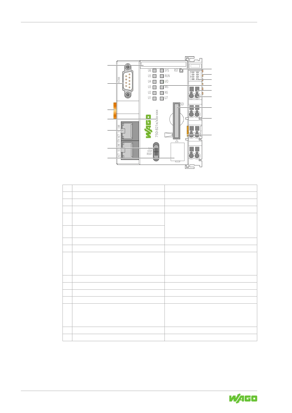
3.1.2 Structure of the Head Stations
Example PFC View
Figure3: Example PFC View
1 Reset button & Product Manual
2 Data contacts
8Data Contacts [}20]
3 Display elements: Power supply status & Product Manual
4 Display elements: System status & Product Manual
5 Access to open the associated CAGE CLAMP
®
con-
nection
8Connect Conductor to CAGE CLAMP® [}50]
6 CAGE CLAMP
®
connection for the power supply
connection
7 Memory card slow with protective flap & Product Manual
8 Power jumper contact (spring)
8Power Jumper Contacts [}21]
9 Release tab 8Snapping the Head Station to the DIN-Rail
[}43]
8Removing a Head Station from the DIN-Rail
[}45]
10 Service interface cover
11 Mode selector switch & Product Manual
12 Network connection & Product Manual
13 Item number
8Product Identification [}17]
14 DIN-rail locking cam 8Snapping the Head Station to the DIN-Rail
[}43]
8Removing a Head Station from the DIN-Rail
[}45]
15 Serial interface (optional) & Product Manual
16 Slot for Mini-WSB (optional)
 Loading...


