EasyManuals Logo

WAGO 750 Series System Manual

WAGO 750 Series
56 pages
To Next Page IconTo Next Page
To Previous Page IconTo Previous Page
Page #14 background imageLoading...
Page #14 background image
Serie 750, 753System Features
14 System manual | Version: 3.0.2
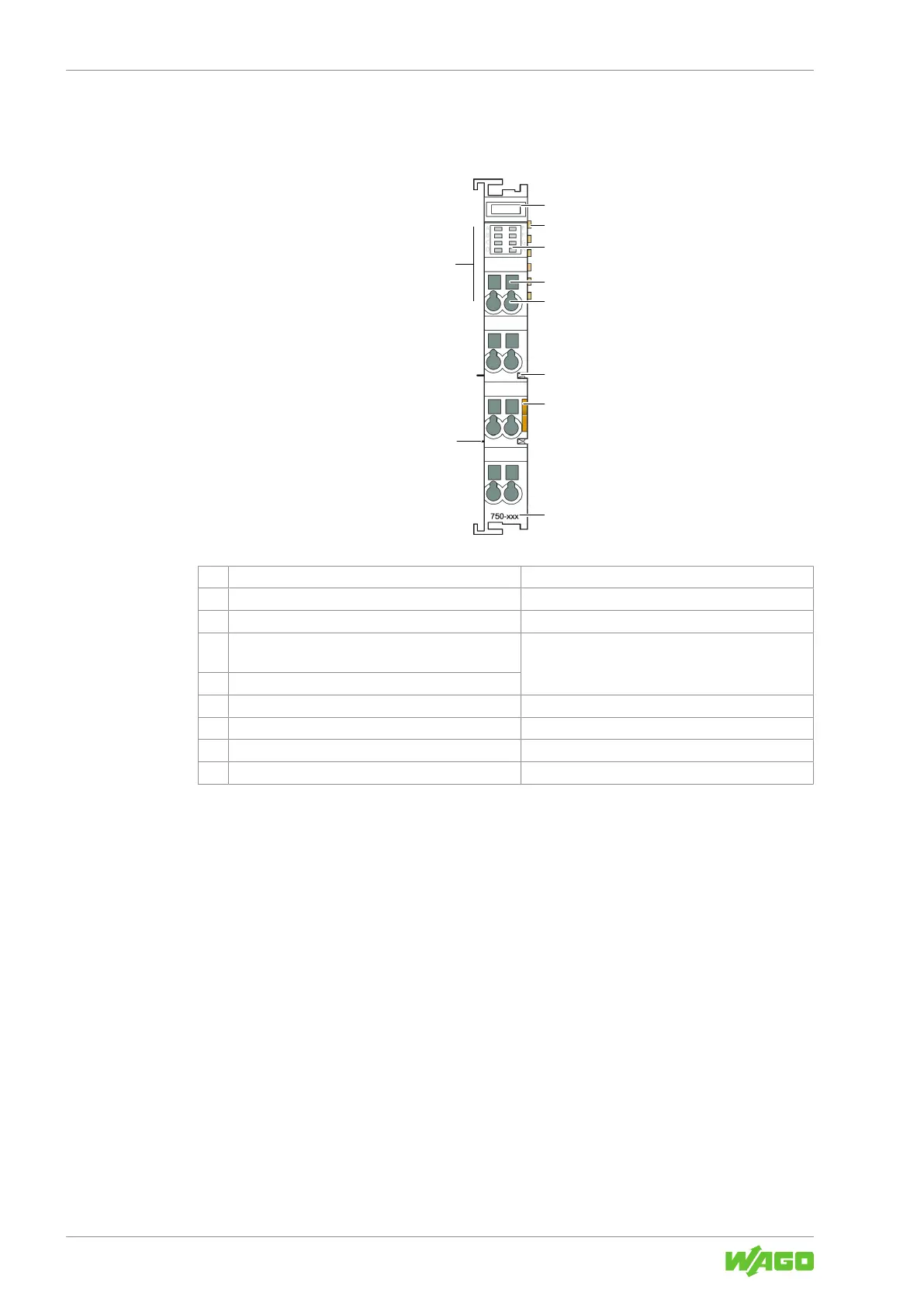
3.1.3 I/O Module Configuration
Example View of the I/O Module 750 Series (CAGE CLAMP
®
Connections)
1
2
2
3
4
5
6
7
8
9
Figure5: I/O module 750 Series with CAGE CLAMP
®
connections (example)
1 Slot for WSB (optional)
2 Data contacts
8Data Contacts [}20]
3 Indicators & Product Manual
4 Access to open the associated CAGE CLAMP
®
con-
nection
8Connect Conductor to CAGE CLAMP® [}50]
5 CAGE CLAMP
®
connection
6 Power jumper contact (spring)
8Power Jumper Contacts [}21]
7 Release tab
8Removing the I/O Module [}46]
8 Item number
8Product Identification [}17]
9 Power jumper contact (blade)
8Power Jumper Contacts [}21]

Table of Contents

Other manuals for WAGO 750 Series

Questions and Answers:

Question and Answer IconNeed help?

Do you have a question about the WAGO 750 Series and is the answer not in the manual?

WAGO 750 Series Specifications

General IconGeneral
Protection ClassIP20
Bus CouplersPROFIBUS, CANopen, Ethernet
ModulesDigital Input, Digital Output, Analog Input, Analog Output
MountingDIN rail mounting
Voltage Supply24 V DC (typical)
Communication ProtocolDepends on the bus coupler (e.g., PROFIBUS, CANopen, DeviceNet, Ethernet)
Digital Input ChannelsVaries by module (e.g., 8, 16 channels)
Digital Output ChannelsVaries by module (e.g., 8, 16 channels)
Analog Input ChannelsVaries by module (e.g., 2, 4, 8 channels)
Analog Output Channels1, 2, 4 channels (depending on module)
Width12 mm, 24 mm (typical module widths)
Number of ChannelsVaries by module type
Current Consumption per ChannelVaries by module type

Related product manuals