16 | CFW701
Installation and Connection
English
Use twisted cable for the connection. Separate these cables from the signal and control
cables.
Size the cables according to the application, respecting the maximum and effective currents.
If the braking resistor is installed inside the inverter cabinet, consider its additional dissipated
energy when sizing the cabinet ventilation.
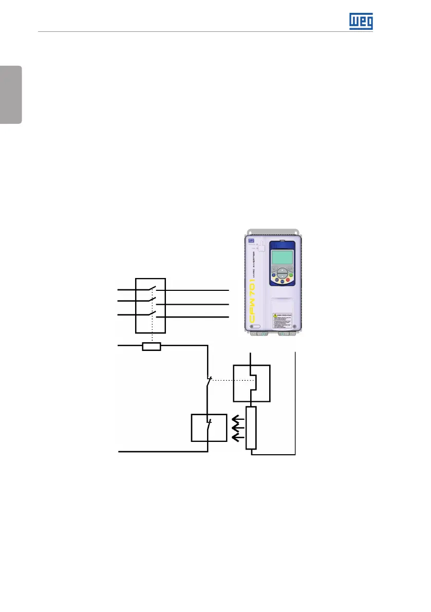
The thermal protection of the dynamic braking resistor must be provided externally using
a thermal relay in series with the resistor and/or a thermostat in contact with the resistor
frame, connected so as to switch the input power supply of the inverter, as shown in Figure
3.3 on page 16.
Set P0151 and P0185 to their maximum values (400 V or 800 V) when using dynamic braking.
The DC link voltage actuation level of the dynamic braking is set by parameter P0153 (Dynamic
Braking Level).
Power
supply
Thermostat
Braking
re sis tor
Thermal
relay
Control power
supply
Contactor
CFW701
BR
DC+
R
S
T
Figure 3.3: Connection of the braking resistor