iPump User’s Manual
800009-01 Rev. A 22 wegener.com
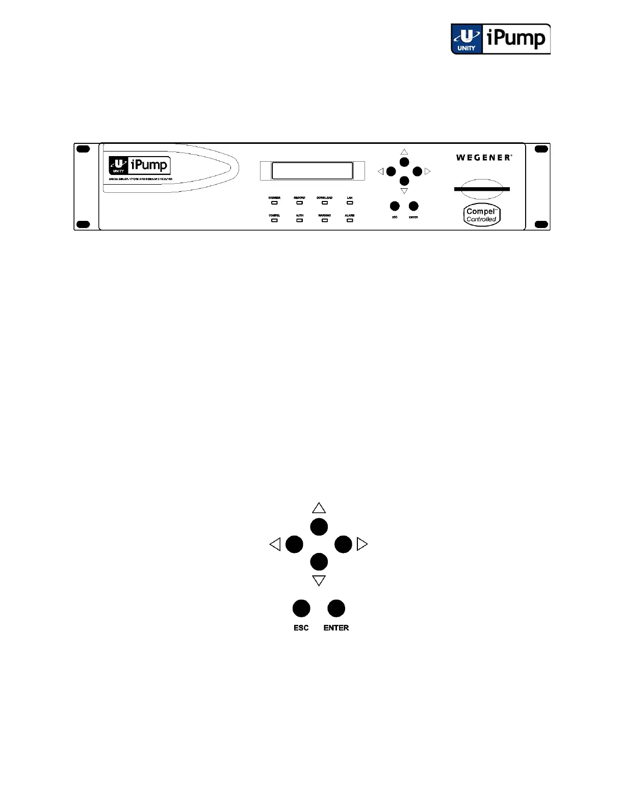
3.2 Front-panel Controls and Indicators
There are three major parts of your iPump's front-panel controls and indicators:
the liquid-crystal display (LCD), the six push buttons, and the eight LED indi-
cators.
Figure 3.1 iPump Front Panel
Liquid-
crystal
Display(LCD)
The iPump's LCD indicates unit status and prompts for and reflects user input.
Here, you will see your iPump's unit label and serial number displayed on the
top line following startup. The home screen also alternately displays the input
signal’s frequency, data rate, and FEC ratio in the lower left corner and contin-
uously displays the current signal-to-noise ratio in the lower right. Using the
adjacent pushbuttons (described in the next paragraph), you can navigate the
iPump's various screens and edit input fields.
Pushbuttons These six pushbuttons are your means of commanding the iPump from the
front panel. The four arrow buttons allow navigation through the menu screens
and parameter selection and editing in user-input screens. The ENTER button
serves to select menu options (downward navigation), to open user-input
fields, or to commit user input to the iPump. Also press ENTER to quickly
start the unit after a normal shutdown. The Escape (ESC) button allows exit
from user-input fields without saving the entry or selection. ESC also provides
upward navigation through the menu structure to the home screen.
Figure 3.2 Pushbuttons