iPump User’s Manual
800009-01 Rev. A 18 wegener.com
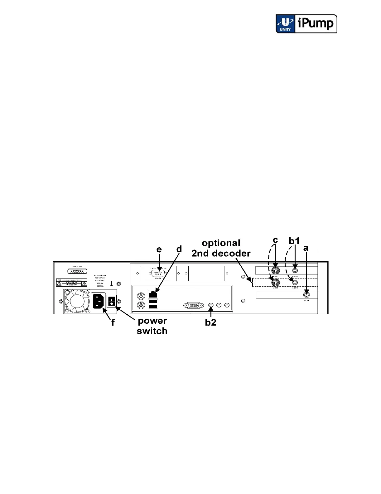
2.3 iPump Connections
Before applying power, make the following connections to your iPump (refer
to Table 4 on page 19 for connector details and to Figure 2.1 iPump Rear-
panel Connector Locations for placement):
a) Connect the L-band output from your antenna's LNB to the extender
cable on your iPump's input RF port [a]. (A BNC connector is used
here for iPumps with the ASI input option.)
b) Connect a suitable audio monitor or monitors to the iPump's audio
port(s) [b1] (on both decoders if your iPump includes a second
decoder). Also connect audio monitoring to the auxiliary audio port
[b2] if your iPump includes that option (See Table 1: iPump Options
Key on page 10).
c) Connect a suitable video monitor or monitors to the iPump's video [c]
port (on both decoders if your iPump includes a second decoder). (See
Table 1: iPump Options Key on page 10).
d) Connect your LAN line to the iPump's Ethernet port [d]. (Refer to
Table 6: iPump LAN Connector Pin Functions on page 20.)
Figure 2.1 iPump Rear-panel Connector Locations
e) If desired, connect the Alarm port [e] to your equipment to provide
contact closures and openings during alarms or on command from
Compel. (Refer to Table 5: iPump Alarm Connector Pin Functions
on page 19.)
f) Finally, connect the supplied ac power cord to the iPump's IEC
receptacle [f] and to a 100-to-120 Vac or 200-to-240 Vac source.
NOTE: Do not connect devices to the mouse, keyboard and other connectors
not described here. They are for factory use only.