上海维宏电子科技股份有限公司
Weihong Electronic Technology Co., Ltd.
Specialized, Concentrated, Focused - 107 -
5.4.2.17 Parameter Setting of Stone GS Servo Driver
Electronic gear
ratio numerator
Electronic gear ratio of position mode: 4× pulse frequency fed
back by servo encoder = command pulse frequency× F0f /
F10; value of F0f / F10 must be within 1/100~100. (calculation
with pitch as 10mm)
Electronic gear
ratio denominator
0: External speed running mode; make sure the value and
direction of motor speed according to the external analog
-10V ~ +10V signal of CN2-16, 17;
1: Internal speed running mode; make sure the value and
direction of motor speed according to the setting of parameter
F33, F35, F37, F39 and the port status of CN2-9, CN2-25;
2: Position pulse running mode; accept the input of external
position pulse and direction level signal;
3: Jog mode; make sure the motor speed in terms of
parameter setting of F3b, and control the rotation direction by
the direction keystroke ▼ and ▲;
4: Torque mode; make sure the value and direction of motor
torque according to the external analog -10V ~ +10V signal of
CN2-43, 1;
5~10: Mixed mode; select mode according to the port input
status of CN2-24:
F00
Value
5
6
7
8
9
10
CN2-24 Interface Status
OFF (Mode One)
Position Pulse Mode
Position Pulse Mode
Position Pulse Mode
Internal Speed Running Mode
Internal Speed Running Mode
External Speed Running Mode
External Speed Running Mode
Torque Mode
Torque Mode
Torque Mode
Internal Speed Running Mode
External Speed Running Mode
ON (Mode Two)
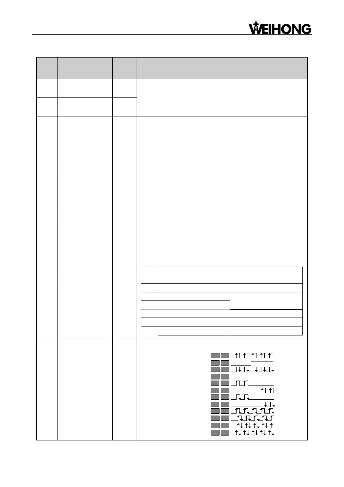
Pulse input mode
selection
Command pulse string mode selection of position mode:
1 – Single pulse
train positive logic
Pulse
Direction
12 27
13 28
2 – Single pulse
train negative logic
Pulse
Direction
12 27
13 28
3 – Double pulse
train positive logic
CCW
CW
12 27
13 28
4 – Double pulse
train negative logic
CCW
CW
12 27
13 28
5 – Orthogonal
pulse positive logic
Phase A
Phase B
12 27
13 28
6 – Orthogonal
pulse negative logic
Phase A
Phase B
12 27
13 28