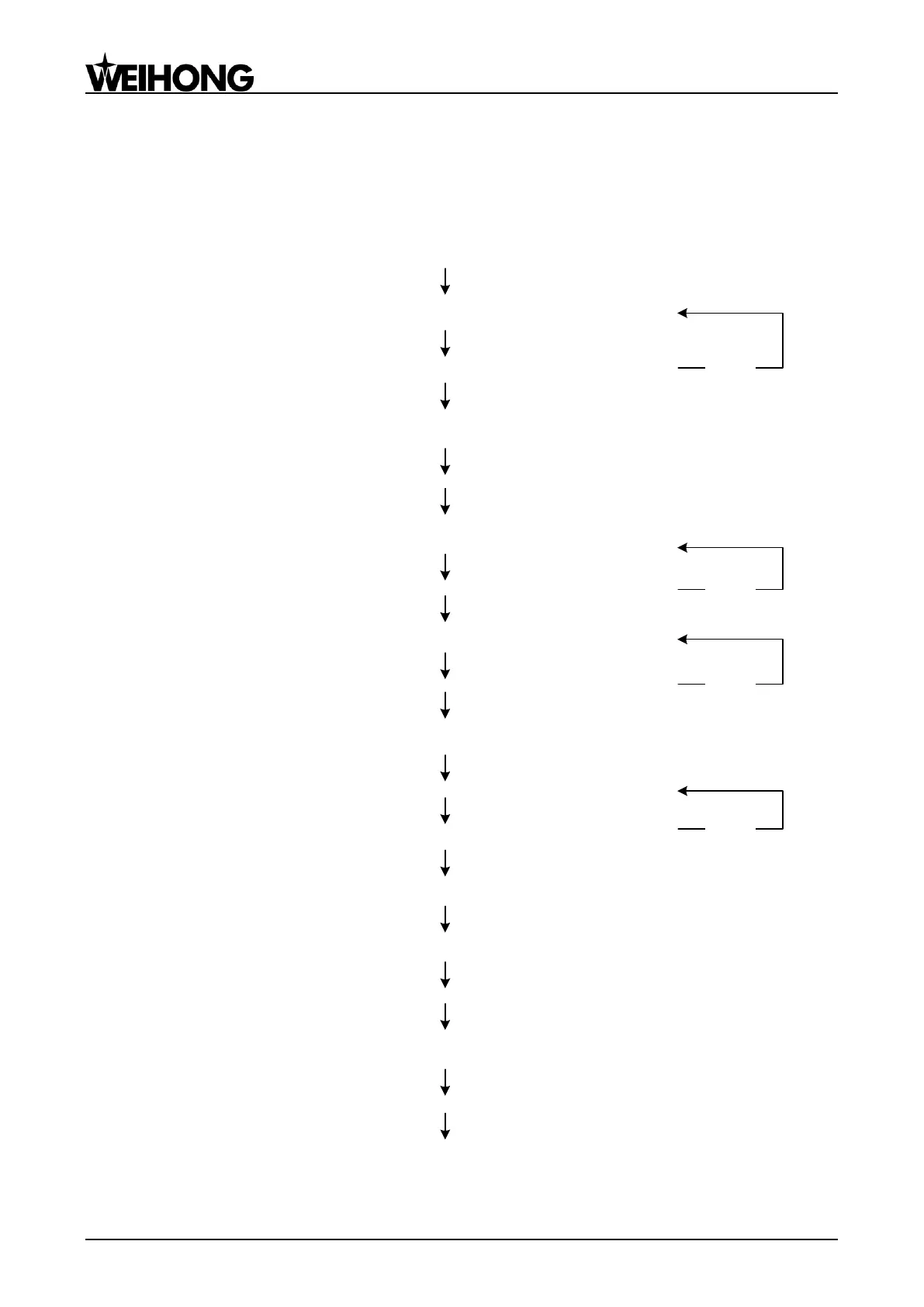
Do connections and supply power
Debugging starts
Power lamps of controller and terminal board, and signal lamp of home
switches are ON
Do connections and power on controller, machine signal system and
terminal board
True
Change port polarity in the software
Change the polarities of inputs according to the hardware (e.g. home
switches, limit switches and E-stop button)
Check connections and short circuit an input and COM on the
controller
The LED of the input turns on and the software receives the signal
Click the ―TestOn‖ and ―TestOff‖ buttons in the software
and see whether the LED of the output changes accordingly
The LED of the output changes accordingly
Set inverter parameters
Set inverter parameters, like max. and min. operating frequency and
source of external command
Check wirings and inverter parameters
Spindle rotates in the right direction and runs at speed according to the
setting value
Set relative parameters of servo driver
Please set them according to Section 5.4
Set pulse equivalent in manufacturer parameters of NcStudio
Please set it according to Section 5.3
Manually move machine tool to confirm the correctness of directions of each axis
Verify the settings of electronic gear ratio and pulse equivalent
Set worktable stroke and back to REF. point parameters in manufacturer parameters
Debugging completed
(1)
(2)
Electrify the electrical box and check
(3)
Check IOs of the controller
(4)
True
True
(5)
(6)
(7)
(8)
(9)
Alter the axis directions in the system manufacturer parameters or the
relative parameters of servo driver
(10)
False
False
False
False
True
Fig. 4-1 Process of machine tool debugging