WM 68071 05/2021
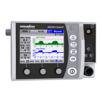
MEDUMAT Standard
2
EN 39
3 Description
No. Designation Description
1 Patient valve Switches between inspiration and expiration.
2
FlowCheck sensor connection line
with MEDUtrigger (only with Flow
measurement + ASB option)
Connects MEDUtrigger and the FlowCheck sensor to
the device. Alternatively, you can also connect the
FlowCheck sensor connection line or the connection
line of MEDUtrigger here.
3
Water filter
(only with Capnography option)
The water filter protects the measuring chamber of
the device against moisture and contamination from
the patient's respiratory gas.
4 Measuring circuit
The device measures the patient's vital parameters
via the measuring circuit. The measuring circuit
comprises:
• Measuring circuit connector
• PEEP control tube
• Pressure measuring tube
•CO
2
measuring tube
(only with Capnography option)
5 Measuring circuit connector
Connects the measuring circuit to the connection
for the measuring circuit on the device.
6 PEEP control tube
The device controls the patient valve and the PEEP
via the PEEP control tube.
7
CO
2
measuring tube
(only with Capnography option)
Measures the CO
2
content in the respiratory gas of
the patient.
8 Pressure measuring tube Measures the ventilation pressure at the patient.
9
Y-piece
(only with Capnography option)
Connects the pressure measuring tube and the CO
2
measuring tube with the elbow of the breathing
circuit.
10
FlowCheck sensor connector (only with
Flow measurement + ASB option)
Connects one of the following connection lines to
the FlowCheck sensor:
• FlowCheck sensor connection line
• FlowCheck sensor connection line with
MEDUtrigger
11 Blanking plug Closes the CO
2
connection
12 Elbow with CO
2
connection
• Connects the rest of the breathing circuit to
the mask or endotracheal tube.
• Enables the connection of the pressure measuring
tube and the CO
2
measuring tube (only with
Capnography option).
13
FlowCheck sensor (only with Flow
measurement + ASB option)
Measures the flow to the patient and to the device.