5-7
Electrical Shock Hazard
Disconnect power before servicing.
Replace all parts and panels before operating.
Failure to do so can result in death or electrical shock.
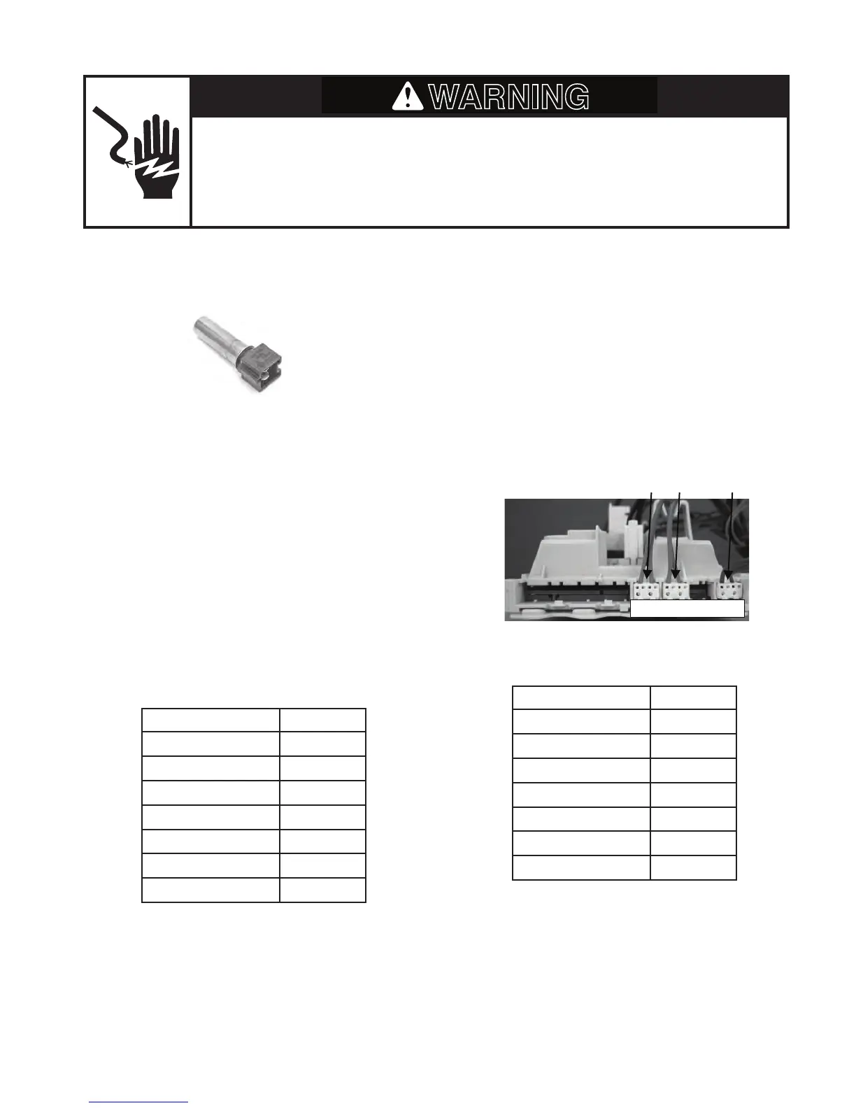
TEMPERATURE SENSOR
Refer to page 4-22 for the procedure for ac-
cessing the temperature sensor .
To check the temperature sensor at the
component terminals, perform the following
steps.
1. Unplug washer or disconnect power.
2. Disconnect the wire connector from the
temperature sensor or heater.
3. Set the ohmmeter to the R X 1K scale.
4. To check the temperature sensor, touch
the ohmmeter test leads to the sensor
terminals. The meter should indicate as
shown in the chart below.
To check the temperature sensor at the CCU,
perform the following steps.
1. Unplug washer or disconnect power.
2. Disconnect the temperature sensor con-
nector SET2 (see page 4-5) from the
CCU.
3. Set the ohmmeter to the R X 1K scale.
4. Touch the ohmmeter test leads to con-
nector pins 1 and 2. The meter should
indicate as shown in the chart below.
Temperature Results
32°F (0°C) 35.9k Ω
86°F (30°C) 9.7k Ω
104°F (40°C) 6.6k Ω
122°F (50°C) 4.6k Ω
140°F (60°C) 3.2k Ω
158°F (70°C) 2.3k Ω
203°F (95°C) 1k Ω
Temperature Results
32°F (0°C) 35.9k Ω
86°F (30°C) 9.7k Ω
104°F (40°C) 6.6k Ω
122°F (50°C) 4.6k Ω
140°F (60°C) 3.2k Ω
158°F (70°C) 2.3k Ω
203°F (95°C) 1k Ω
Temperature
Sensor
SET2 TemperatureSensor
DU3 Door Switch
PR2 Pressure switch Input low voltage