5-3
9 10 11
8
1 2 3 1 2
1 2
21
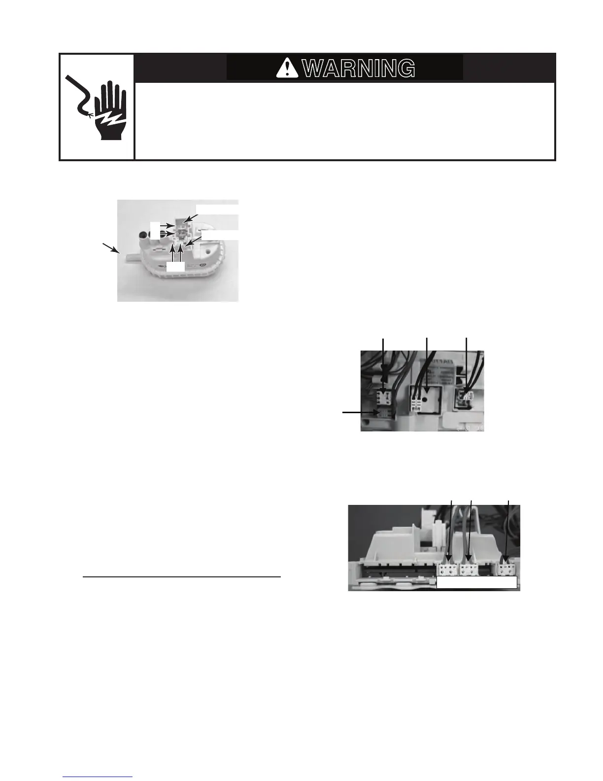
8. MS2 Motor Supply 10. IF2 RFI filterDoor Switch
9. DLS3 Door Lock 11. PRS2 Safety level of Pressure switch
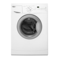
PRESSURE SWITCH
Electrical Shock Hazard
Disconnect power before servicing.
Replace all parts and panels before operating.
Failure to do so can result in death or electrical shock.
Refer to page 4-7 for the procedure for ac-
cessing the pressure switch.
To check the pressure switch contacts at the
component terminals, perform the following
steps.
1. Unplug washer or disconnect power.
2. Disconnect the wire connectors and hose
from the pressure switch.
3. Set the ohmmeter to the R X 1 scale.
4. Touch the ohmmeter test leads to the
pressure switch connector pins shown
below. Blow into the hose inlet of the pres-
sure switch to activate the diaphragm.
The meter should indicate 0 Ω for each
measurement while the diaphragm is
activated.
Water Level Setting Test Points
Safe Level Pins 1 and 2
Low Range Pins 1 and 2
To check the pressure switch at the CCU, per-
form the following steps.
1. Unplug washer or disconnect power.
2. Disconnect pressure switch connector
PRS2 (see page 4-5) from the CCU.
3. Set the ohmmeter to the R X 1 scale.
4. Touch the ohmmeter test leads to con-
nector pins 1 and 2 on PRS2. The meter
should indicate 0 Ω.
Hose Inlet
SET2 TemperatureSensor
DU3 Door Switch
PR2 Pressure switch Input low voltage
4a. Touch the ohmmeter test leads to con-
nector pins 1 and 2 on PR2. The meter
should indicate 0 Ω.
Safe Level
Low Range
1 2
1 2