5-6
Electrical Shock Hazard
Disconnect power before servicing.
Replace all parts and panels before operating.
Failure to do so can result in death or electrical shock.
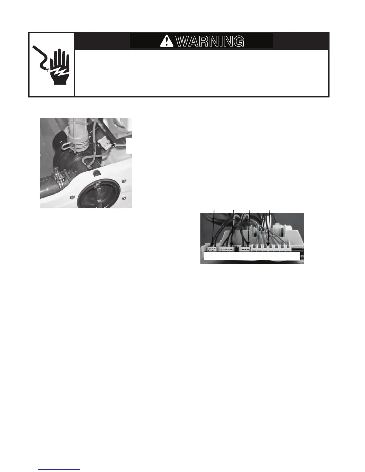
DRAIN PUMP
Refer to page 4-17 for the procedure for ac-
cessing the drain pump.
To check the drain pump at the component
terminals, perform the following steps.
1. Unplug washer or disconnect power.
2. Disconnect the wire connector from the
drain pump.
3. Set the ohmmeter to the R X 1 scale.
4. Touch the ohmmeter test leads to the
drain pump terminals. The meter should
indicate approximately 28 Ω.
To check the drain pump at the CCU, perform
the following steps.
1. Unplug washer or disconnect power.
2. Disconnect the drain pump connector
DP2 (see page 4-5) from the CCU.
3. Set the ohmmeter to the R X 1 scale.
4. Touch the ohmmeter test leads to con-
nector pins 1 and 2. The meter should
indicate approximately 28 Ω.
Drain Pump
Connector
1. DP2 Drain Pump
2. VPW3 & VW3 Cold / Bleach Valve
3. VHF3 Hot Valve
4. M7 Universal Motor
12
4
1 2 1 2 3 1 2 1 2 3 4 5 6 7