32
3. For the Electrician
3. For the Electrician
3.1 Electrical connections
The boiler and related accessories are designed to be installed only in dry areas (protection type IP 10). Instal-
lation of electrical components may only be performed by a qualified technician. The regulations and specifica-
tions of ÖVE, VDI, SEV and local ordinances must be followed.
Attention!
– The mains connection must be protected against short circuit with a 13 A delayed-action fuse.
– On site, the technician must install an all-pole disconnection with at least 3 mm contact gap at
the mains access point. Current-operated r.c.d. or frequency conversion protection switches
are considered all-pole disconnections (ÖVE regulation).
The boiler is pre-wired and internally fused with a T 6.3 A fine-wire fuse to protect against short circuit. If an
MESplus module is ordered (including boiler sensor), this will be installed in FireWIN and electrically wired at
the factory. When there are several MESplus modules, they are all installed in the wall-mount casing to facilitate
operation:
Maximum MESplus module switching capacity: Relay outputs: 230 VAC, 6 A (2 A inductive), 50 Hz
WVF and B-PLM modules with X1/X2 contact: Solid-state relay: 230 VAC, 1 A
The electrical power consumed depends on whether a fully automated pellet feed (suction turbine) is connected,
and on the number of actuators supplied (pumps, mixing valves, etc.).
In areas with increased power surge risk (e.g., lightning strikes in regions prone to storms), we recommend
installation of an appropriate surge protector.
Information!
Be sure to note the separate wiring of the extra-low voltage line (sensor) and low-voltage line (230 VAC)!
Electrical cables must not touch heating and exhaust pipes, nor must they come in contact with
noninsulated boiler components. They are to be sufficiently braced and provided with a protective
tube.
3.1.1 Electrical connection of the FireWIN
We recommend using fine-wire PVC sheathed cables, e.g., H05VV-F (YMM-J) with a 3 x 1.5 mm
2
nominal crosssec-
tion.
Electrical power supply 230 VAC (mains power plug) and the control panel with all electrical connections are
located behind the right side panel cladding. The mains plug, safety thermostats, fuse and MESplus module are
located on the outside of the control panel. The control panel includes the main board and the connection termi-
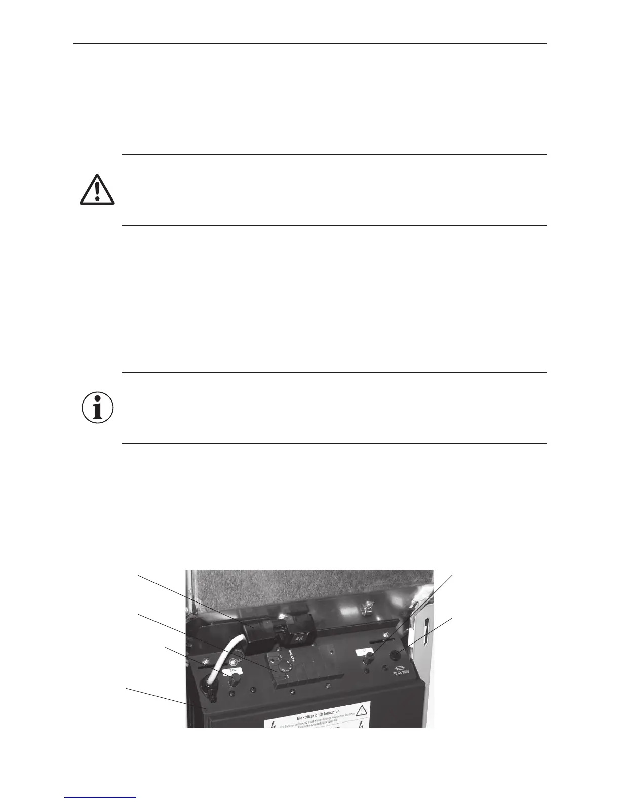
nals (screwless spring-type terminal) for connecting the control system– Fig. 42.
Fig. 42 Control panel
Mains power plug
(230 VAC)
MESplus module
Cover of safety thermostat
auger tube
Control panel
Cover of safety thermostat
Fuse T 6.3 A