Operation0515−1/A1
Winterthur Gas & Diesel Ltd.
6/ 8
3.3.3 Rail Valve
Replace the defective rail valve as soon as possible. Do the procedure that follows:
Note: It is possible to replace a defective rail valve during operation.
1) In the remote control, use the parameter Inj. Cut off to cut out the related cylinder
(see 4002−3, paragraphs 1 and 1.1).
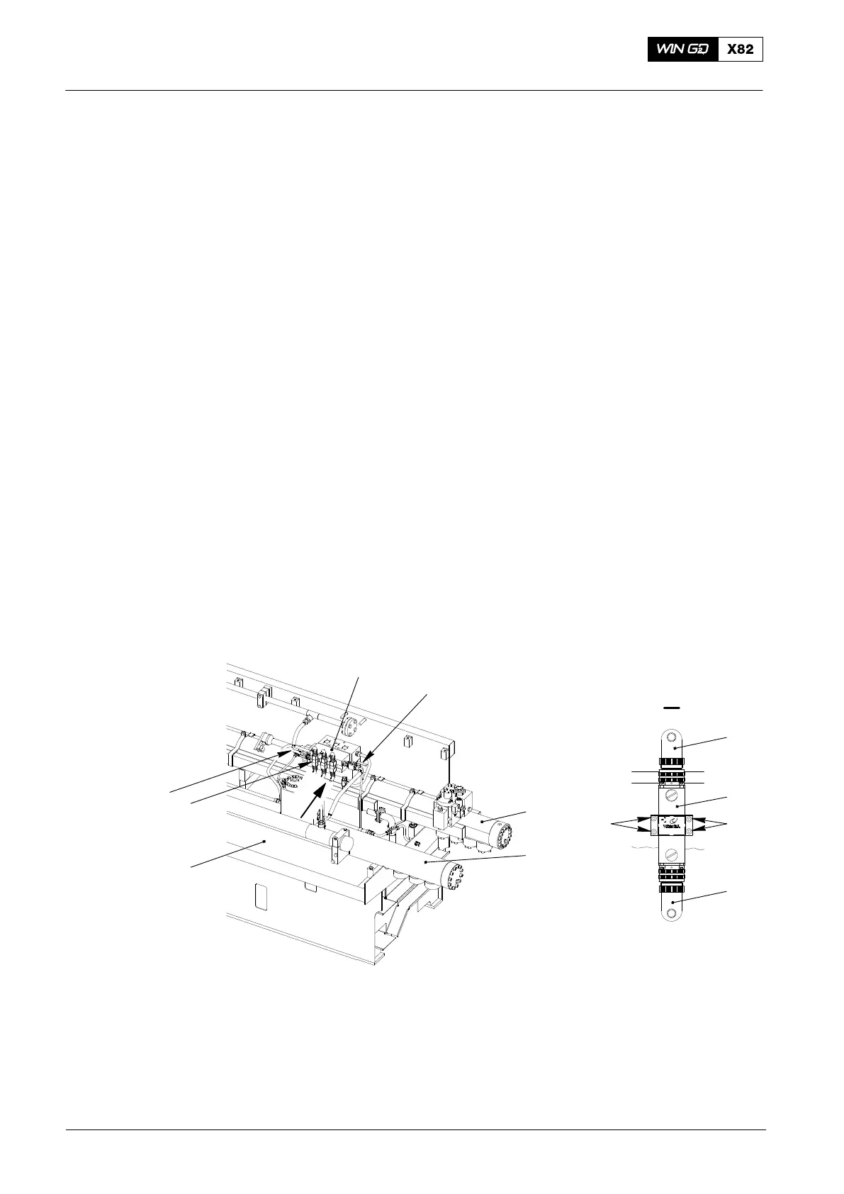
2) Close the ball valve (2) upstream of the injection control unit (1).
3) Close the ball valve (7) downstream of the injection control unit (1).
4) Disconnect the two electrical connections (8) from the rail valve (6).
5) Remove the four screws (9) and the defective rail valve (6) at the same time.
6) Make sure that the three O-rings are installed in the new rail valve and their
surfaces are clean.
7) Apply Never-Seez NSBT-8 to the threads of the four screws (9).
8) Put the new rail valve (6) and screws (9) in position on the injection control
unit (1). You must make sure that the bores are aligned.
9) Torque the four screws (9) to 2.5 Nm (see 5564−1 Injection Control Unit in the
Maintenance Manual).
10) Connect the electrical connections (8) to the rail valve (6). Make sure that the
electrical connections are tight.
11) Open the ball valve (7) downstream of the injection control unit (1).
12) Open the ball valve (2) upstream of the injection control unit (1).
13) In the remote control, use the parameter Inj. Run to cut in the related cylinder
(see 4002−3, paragraphs 1 and 1.1.
I
6
010.153/02
8
8
3
1
6
5
4
018.063/09
DRIVING END
9 9
I
7
2
Fig. 3: Injection Control Unit
1 Injection control unit 3.02 6 Rail valve 3.76
2 Ball valve 3.38 7 Ball valve 3.27
3 Fuel rail 3.05 8 Electrical connection
4 Servo oil rail 4.11 9 Screw
5 Rail unit
2014
Faults in High Pressure Fuel System
 Loading...


