Operation1903−1/A1
Winterthur Gas & Diesel Ltd.
2/ 2
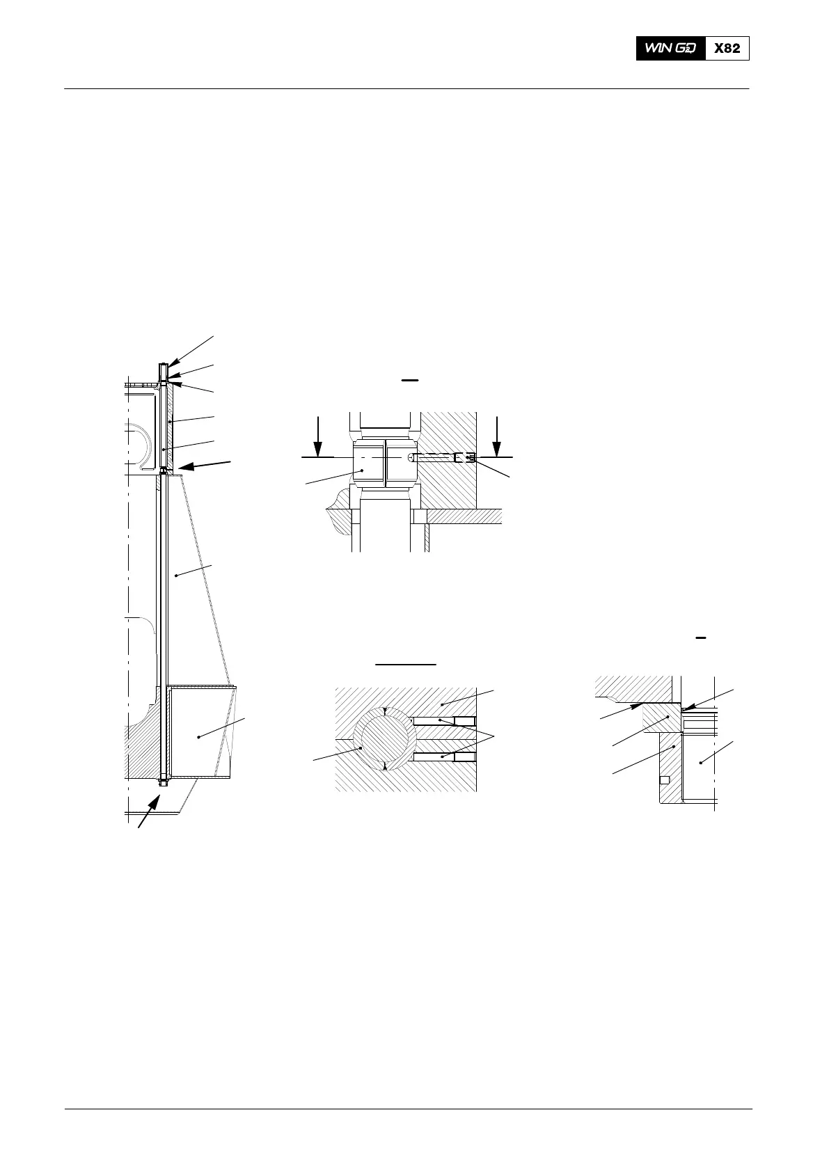
A two-part bush (2, Fig. 2) is welded on the tie rod (1) as shown in view II. At the
bottom of the cylinder block, two set screws (7) tightly hold the two-part bush (2) and
prevent vibration of the tie rods (1).
The space around the bottom part of the tie rod (1) up to the middle of the
column (10) is filled with oil, which also prevents vibration. The oil enters through a
bore from the crosshead guide plate.
The bottom of the intermediate ring (4) has a drain groove DG through which some of
the oil can drain. Possible condensation can also drain through DG (if the engine has
stopped).
10
1
9
3
5
6
II
11
I
II
III III
III - III
2
1
I
DG
4
5
8
7
9
WCH01187
WCH01187
WCH01187
WCH01187
7
2
Fig. 2: Tie Rod Assembly
1 Tie rod 8 O-ring
2 Two-part bush 9 Cylinder jacket
3 Intermediate ring (top) 10 Column
4 Intermediate ring (bottom) 11 Bedplate
5 Round nut
6 Protection cover
7 Set screw DG Drain groove in intermediate ring
2014
Tie Rod