Operation
8017−1/A1
Winterthur Gas & Diesel Ltd.
3/ 4
DP
CW
WO
WI
VEN
5
4
3
2
18
6
7
16
15
10
7
11
19
ENGINE
PLANT
ENGINE
PLANT
3014
3017
308
3014
301
309
30143017
WD
3013
12
CD
3020
SAC Cooling
Water Drain
See Fig. 2
WCH01152
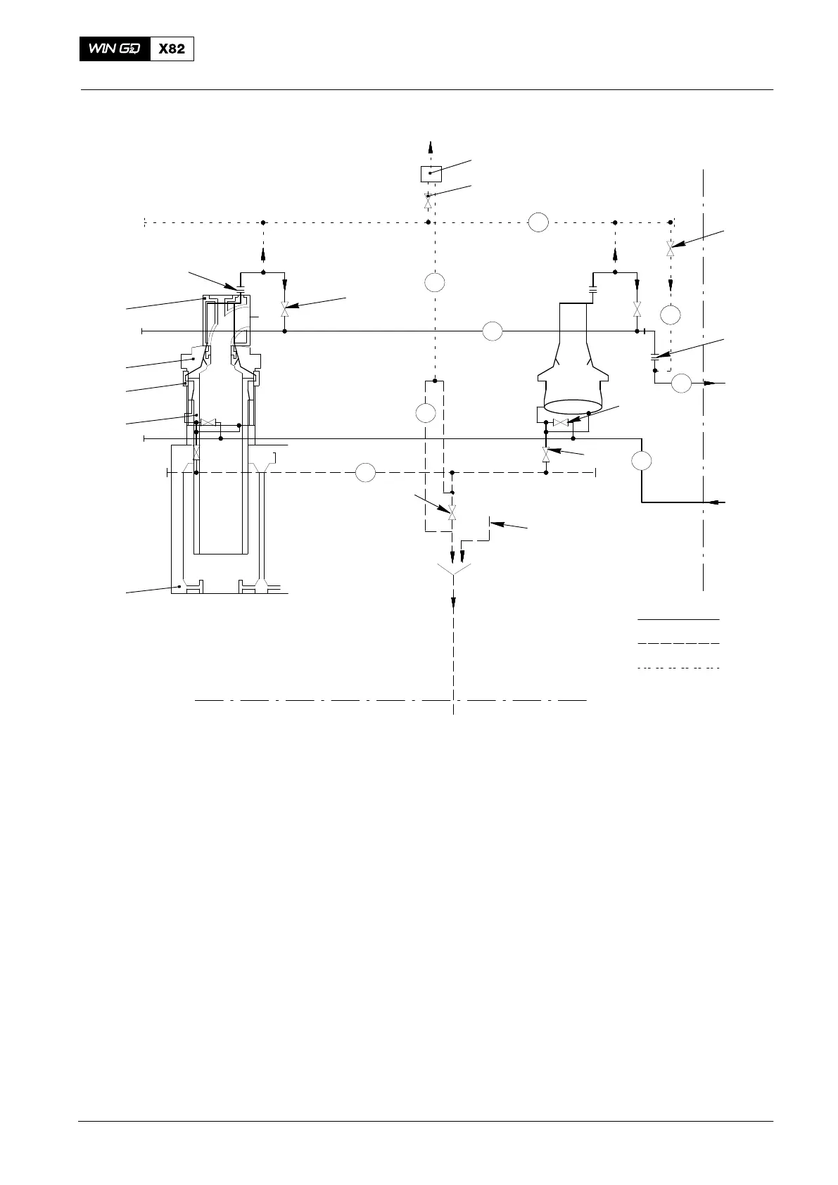
Fig. 1: Cylinder Cooling Water
1 Inlet pipe 15 Ball cock
2 Cylinder liner 16 Vent unit
3 Water guide jacket 17 Condensate drain pipe
4 Cylinder cover 18 Cylinder jacket
5 Exhaust valve cage 19 Ball cock
6 Throttle (cylinder outlet) 20 Cylinder drain pipe
7 Shut-off valve (at cylinder)
8 Outlet collector pipe
9 Outlet pipe WD Water drain
10 Adjustable throttle (water outlet) CW Cooling water
11 Shut-off valve (cylinder drain) WO Cooling water outlet
12 Ball cock (for condensate drain) WI Cooling water inlet
13 Bypass pipe DP Drain pipe
14 Vent pipe CD Cylinder drain
2014
Cooling Water System
 Loading...


