Maintenance
2124−1/A1
RT-flex58T-D
Winterthur Gas & Diesel Ltd.
1/ 1
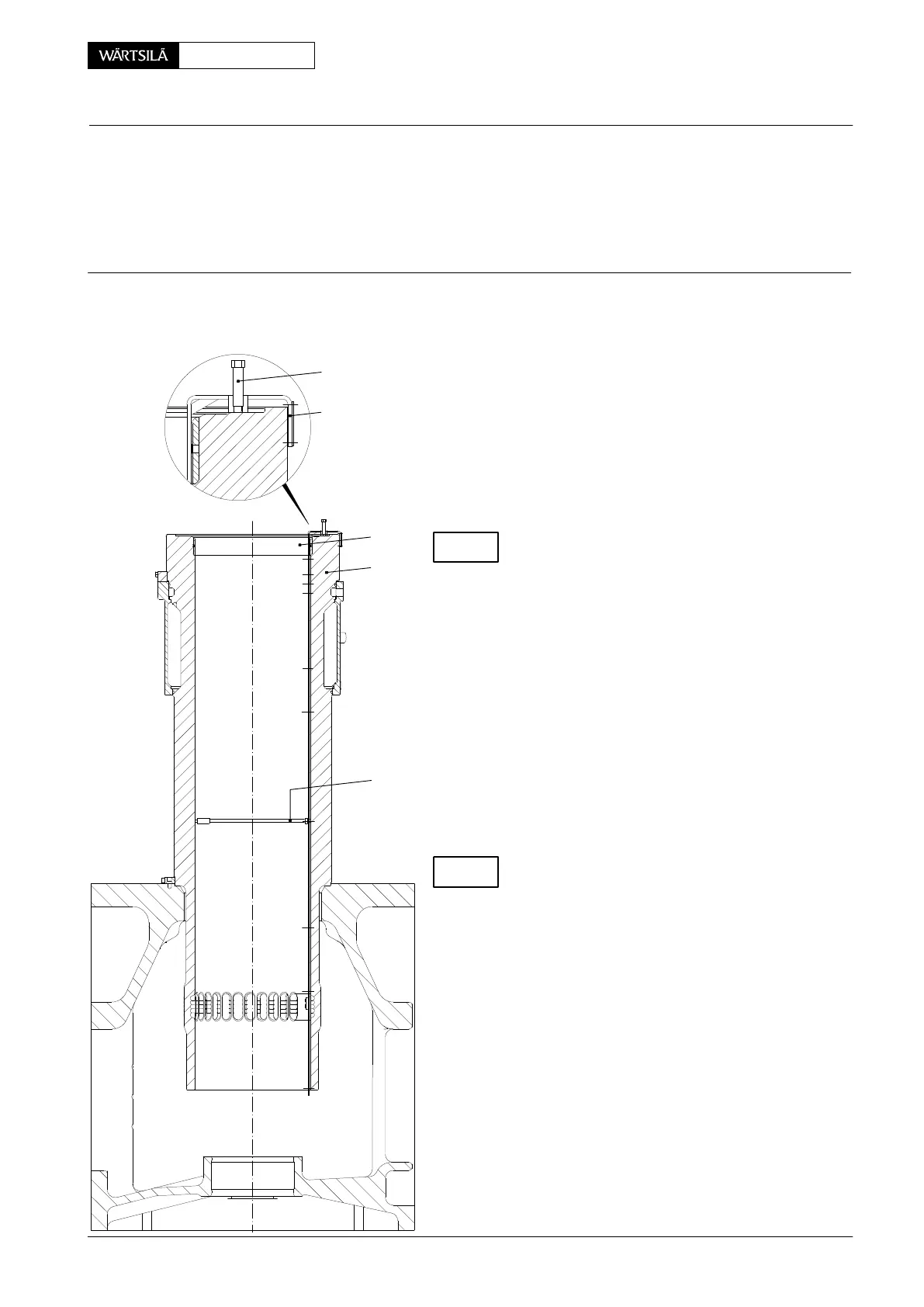
Tools: Key to Illustrations:
1 Inside micrometer 94101 1 Cylinder liner
1 Measuring gauge 94225 2 Antipolishing ring
ST Setting screw
⇒ The cylinder liner wear is to be determined af-
ter every piston removal with the cylinder liner
in situ.
⇒ To permit comparisons with previous mea-
sures always carry out measuring in the same
place and note down the values in a log.
⇒ Always use the properly adjusted measuring
gauge 94225.
Check setting screw ’ST’. Its lower protruding
length must correspond to the mean thickness
of the built-in compression shims. This ensur-
es that the topmost measuring point is located bet-
ween the top ring wear ridge and the antipolishing
ring.
The unrun position must be thoroughly
cleaned from any deposits or lacquer before
measurement.
⇒ Hook the measuring gauge over the top face
of the cylinder liner.
⇒ The measurements have to be taken in longi-
tudinal and transversal directions to the en-
gine axis by putting the inside micrometer
94101 into the holes provided in the measur-
ing gauge.
For maximum permissible inside diameter refer to
Clearance Table 0330−1 ’Cylinder liner’.
⇒ The ridge at the top of the cylinder bore has to
be removed carefully without damaging the
running surface for the piston rings (see
2124−3).
⇒ Remove the lower part of the measuring
gauge 94225 for measuring the cylinder liner
with piston in situ. Turn piston to B.D.C.
Cylinder Liner
Measuring Bore Wear
V2 / 2013-02
94101
SETTING SCREW ’ST’ DRAWN FOR COM-
PRESSION SHIM THICKNESS = 0 mm.
WCH0100
ST
94225
1
2
CHECK
CHECK
 Loading...


