Maintenance
5556−1/A1
RT-flex58T-D
Winterthur Gas & Diesel Ltd.
1/ 10
Tool: Key to Illustrations:
1 Handle screw 94009−M6 1 Actuator 23 Screw
1 2-part clamping ring 94550 2 Connecting element 24 Flange
1 Fitting & dismantling device 94551 3 Screw 25 Regulating (toothed) rack
1 Cover 94552 4 Pump cover 26 Circlip
1 Spacer 94555 5 Upper housing 27 Stop ring
1 Checking gauge 94556 6 Lower housing 28 Allen screw M16x220
7 Guide piston 29 Valve block
8 Roller 30 Valve body
9 Guide pin 31 Compression spring
10 Pin 32 Holding screw (Cu-ring)
11 Circlip 33 Pump cylinder
12 Pressure disc 34 Intermediate disc
13 Bush 35 Circlip
14 Snap ring 36 Screw
15 Pin 37 Bush
16 Allen screw 38 Rod seal ring
17 Lower spring carrier 39−41 O-rings
18 Pump plunger
19 Compression spring
20 Guide pin
21 Regulating sleeve DS Pressure piece
22 Upper spring carrier RC Eye bolt M6
Overview
1. Preparation 1/10...........................................
2. Removal of a fuel pump 2/10...............................
3. Dismantling of a fuel pump 3/10............................
4. Assembling of a fuel pump 7/10............................
5. Fitting of a fuel pump 10/10.................................
6. Preserving 10/10...........................................
1. Preparation
⇒ Stop the engine and switch off the fuel supply
pump.
⇒ Close shut-off valves to the fuel inlet and out-
let pipes, as well as the pressure retaining
valve.
(see 0720−1 in the Operating Manual).
⇒ Remove the fuel inlet and outlet pipes.
⇒ Remove the fuel pressure piping (see
8752−1).
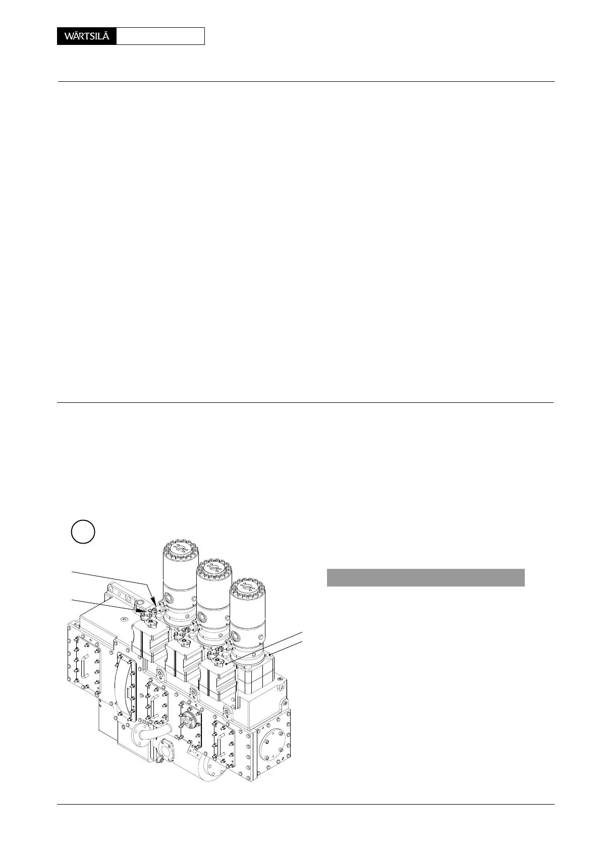
⇒ Remove connecting element 2 between reg-
ulating rack 25 of fuel pump and actuator 1.
A
WCH01085
25
2
1
3
V2 / 2013
Fuel Pump
Dismantling and Assembling
 Loading...


