Maintenance
3326−2/A1
RT-flex58T-D
Winterthur Gas & Diesel Ltd.
1/ 6
Tools: Key to Illustrations:
1 Manual ratchet (WLL 800 kg) 94016 (H1) 1 Crank
2 Manual ratchets (WLL 1000 kg) 94016D (H2, H3) 2 Connecting rod
1 Manual ratchet (WLL 2500 kg) 94016E (H4) 3 Piston rod
1 Manual ratchet (WLL 250 kg) 94016G (H5) 4 Crosshead pin
1 Spur-geared chain block (WLL 3000 kg) 94017A (H6) 5, 5a Guide shoe
4 RUD-eye bolts (RC1) 94040−M20 6, 6a Guide shoe middle part
2 RUD-eye bolts (RC2) 94040−M30 7 Guide rail
1 Eye bolt (RC3) 94045−M10 8 Screw
1 Deviation pipe GF 94117A 9, 9a End cover
1 Working platform 94142 10 Guide way
2 Cover and lifting plate 94324
2 Holders 94325
1 Wire rope sling GF 94333D
3 Shackles (WLL 4750 kg) 94572C
2 Shackles (WLL 2000 kg) 94572I WU Wooden underlay
1. General
Risk of accident! Ensure that the crankshaft does not turn unintentionally during
all the work.
Remark: Pay attention to:
− General Guidelines for Lifting Tools 0012−1.
− Utilization of Working Platform 3301−1.
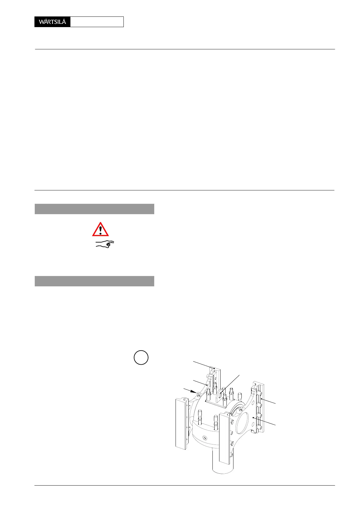
2. Preparatory works
D Top end bearing cover removed (see 3303−5) and piston rod 3 suspended.
D Platform element removed.
D Relevant cylinder turned to B.D.C.
D Lifting plate 94324 mounted on crosshead pin.
D Two RUD-eye bolts ’RC1’ tightened to middle parts 6, 6a with 115 Nm.
94324
RC1
6a
6
5a
5
A
V2 / 2013
Crosshead
Removal and Fitting of a Crosshead Pin
 Loading...


