Maintenance
2751−1/A1
RT-flex58T-D
Winterthur Gas & Diesel Ltd.
1/ 5
Tools: Key to Illustrations:
1 Dismantling tool 94008A−M68 1 Elastic stud 6 Expansion piece
2 Pre-tensioning jacks 94252 2 Nut 7 Protection pipe
1 Valve protector 94262 3 Valve cage
1 Wire rope sling GF 94333D 4 Valve seat RC Eye bolt
2 Lifting lugs 94811 5 Valve spindle RS Round bar
1 Hydr. distributor 94932
1 Hydr. distributor 94934A
1 HP hose 94935
2 HP hoses 94935A
1 Hydraulic unit 94942
1. General
Prior to the removal of an exhaust valve, drain first the cylinder cooling water from
the respective cylinder (see 2708−1), and close the air inlet to the air spring at the
control air supply (see 0520−1 in the Operating Manual).
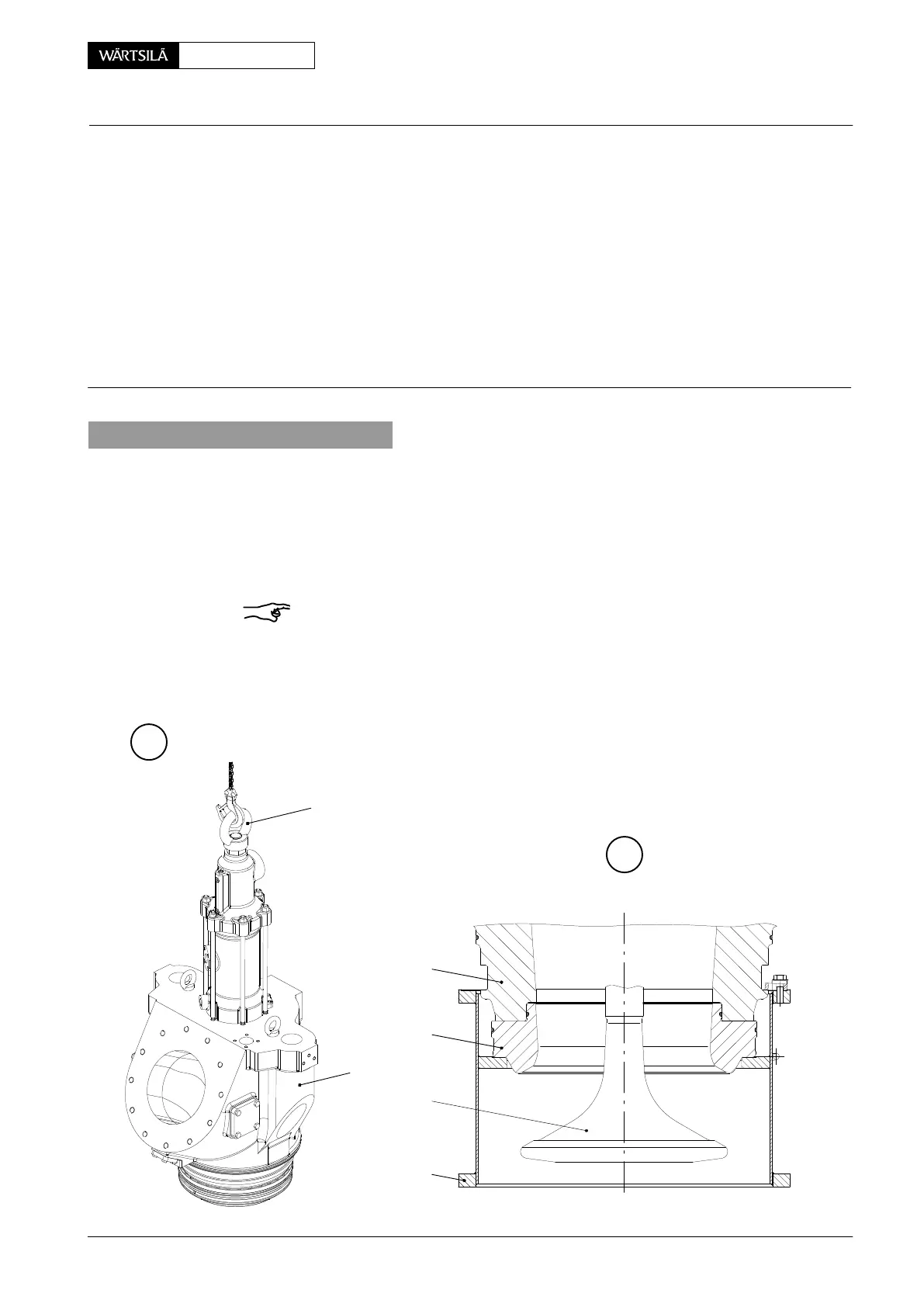
The exhaust valve can be removed from the cylinder cover or transported with the
eye bolt ’RC’.
The valve cage must be suspended as shown in Fig. ’A’.
Remark: Pay attention to:
− General Guidelines for Lifting Tools 0012−1.
− General Application Instructions 9403−4 for hydraulic pre-tensioning jacks.
D If the exhaust valve is not to be dismantled at site immediately, mount the
valve protector 94262.
B
003.352/00
5
94262
3
3
RC
WCH01037
4
A
V2 / 2013
Exhaust Valve
Removal and Fitting of Exhaust Valve, Replacing of Elastic Studs
 Loading...


