Maintenance
5612−1/A1
RT-flex58T-D
Winterthur Gas & Diesel Ltd.
1/ 3
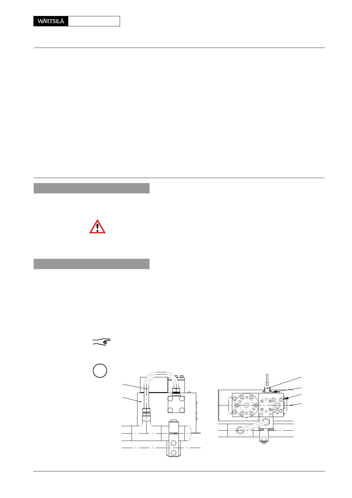
Key to Illustrations:
1 Valve control block 15 Slide rod
2 Pipe 16 Screw plug
3 Rail valve (pre-control valve) 17 Screw
4 Screw 18 Screw plug
5 Screw 19 Filter
6 Servo oil rail 20 Screw plug
7 Dowel pin 21 Filter
8 Connecting block 22 Throttle
9 Screw 23 Screw
10 Cover 24 Plug
11 Piston 25 O-ring
12 Screw 26 O-ring
13 Cover 27 O-ring
14 Compression spring 28 O-ring
1. General
When working on the exhaust valve control unit in principle the engine has to be
stopped.
Attention! HP Servo oil pipes must be pressureless. Follow the instruction in
0520−1 of the Operating Manual without fail!
The respective work station must be clean; welding and grinding should not be
done nearby!
2. Removal
⇒ For dismantling the exhaust valve control unit, first remove the hydraulic pipes
from the exhaust valve control unit (see 8460−1).
⇒ Remove pipes 2.
⇒ Disconnect plugs 24 from rail valve 3.
⇒ Loosen screws 4.
⇒ Carefully lift the complete exhaust valve control unit.
Remark: Immediately cover the appearing opening in servo oil rail 6 and pipes to
prevent dirt from entering in any circumstance!
A
2
1
3
015.975/07
6
24
4
2013
Exhaust Valve Control Unit
Removal, Fitting, Dismantling and Assembling
 Loading...


