Maintenance
8752−1/A1
RT-flex58T-D
Winterthur Gas & Diesel Ltd.
1/ 5
Tools: Key to Illustrations:
1 Regrinding device 94870 1 Upper HP fuel pipe 13 Screw
consisting of: 2 Lower HP fuel pipe 14, 14a Flange
1 Screw-on sleeve 94870E 3 Fuel rail 15, 15a Screw
1 Grinding tool 94870F 4 Fuel pump cover 16 Non-return valve
1 Lock nut 94870G 5 Intermediate piece 17 Leakage fuel pipe
1 Template 94870H 6 Mounting clamps 18 Claw
7 Screw 19, 20 O-ring
1 Torque wrench 8 Screw 21 Thrust ring
9 Flange DF Sealing face
10, 10a Intermediate ring EC Emery cloth
11 Valve housing HD Hand drill
12 Flange LB Leakage fuel bore
A
WCH01047
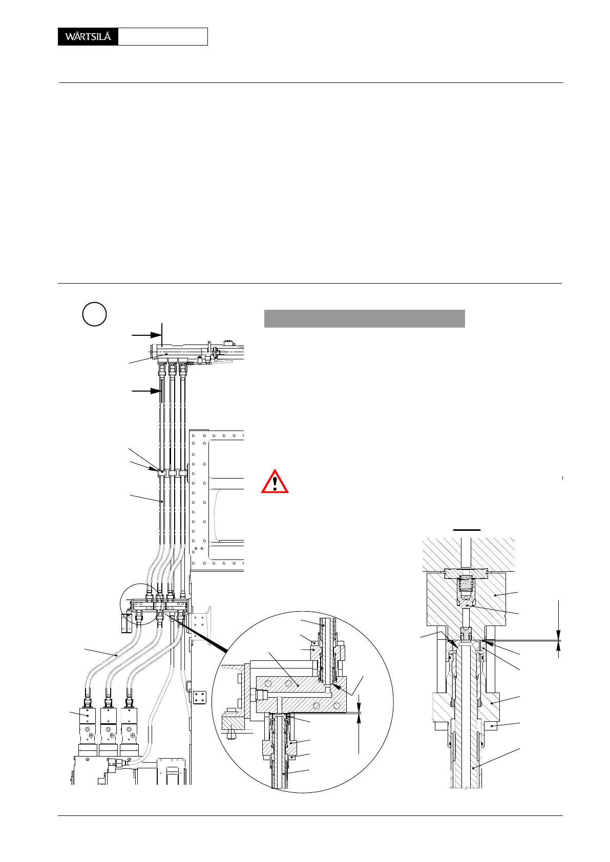
1. General
The engine must be stopped and the fuel supply pu
switched off. After approx. 10 minutes the pressure is reduc
in the HP fuel pipe and the fuel can be drained as follows:
⇒ Loosen screws 8, push back flange 9 and intermediate ri
10 (section I-I) in order to vent the pipe for draining.
⇒ Loosen screws 13, push back flange 12 and separ
lower HP fuel pipe 2 from its sealing faces. Fuel oil drai
via bores ’LB’ and leakage fuel pipe 17 (section II-II)
Non-return valves 16 prevents the fuel rail from dischargin
Risk of accident! Make sure that the steam supply is clos
before loosening the screwed connections to the heating pip
3
I - I
WCH01051
I
I
6
7
5
1
15
14
10a
14a
15a
2
11
16
10
9
8
1
DF
DF
2 mm
2 mm
20
4
1
2
HP Fuel Pipe
Removing, Fitting and Regrinding
V2 / 2013
 Loading...


