Page 2 of 46
WITT-GASETECHNIK GmbH & Co KG
Gas Safety- & Control Equipment
1 Table of contents
1 Table of contents......................................................................................................... 2
2 Notes on these operating instructions ...................................................................... 4
2.1 Scope................................................................................................................................................... 4
2.2 Structure .............................................................................................................................................. 4
2.3 Rights to this manual ........................................................................................................................... 5
2.4 What symbols are used? ..................................................................................................................... 5
3 Safety instructions and precautionary measures .................................................... 6
3.1 General safety guidelines .................................................................................................................... 6
3.2 Measurement of burnable gases ......................................................................................................... 7
3.3 Liability for proper function or damage ................................................................................................ 7
4 Equipment description ............................................................................................... 8
4.1 Intended use of the analyser ............................................................................................................... 8
4.2 Functional description.......................................................................................................................... 8
4.2.1 Technical data of the analyser ................................................................................................. 9
5 Set up and installation .............................................................................................. 10
5.1 Checking for transport damage ......................................................................................................... 10
5.2 Location for setting up ....................................................................................................................... 10
5.3 Safety instructions for installation ...................................................................................................... 10
5.4 Installation of gas pipes ..................................................................................................................... 11
5.5 Electrical installation .......................................................................................................................... 12
6 Commissioning and operation ................................................................................. 13
6.1 Safety instructions for commissioning and operation ........................................................................ 13
6.2 Commissioning and operating of the analyser .................................................................................. 13
6.3 Calibration check / Calibration of the selected gas combination ....................................................... 14
6.4 Shut-down ......................................................................................................................................... 15
6.5 Malfunctions and rectification ............................................................................................................ 15
6.5.1 Malfunction table .................................................................................................................... 15
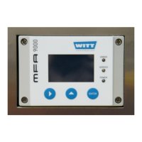
7 Operation of the analyser module ........................................................................... 17
7.1 The Front Panel ................................................................................................................................. 17
7.1.1 Process Alarm and System Error Indicators .......................................................................... 17
7.1.2 System Alarm Indicator (red) ................................................................................................. 17
7.1.3 System Maintenance Indicator (yellow) ................................................................................. 17
7.1.4 Operation Indicator (green) .................................................................................................... 17
7.1.5 RIGHT / Selection Key ........................................................................................................... 18
7.1.6 UP / Selection Key ................................................................................................................. 18
7.1.7 ENTER / Termination Key ...................................................................................................... 18
7.2 Front Panel Menu .............................................................................................................................. 18
7.2.1 Warm up Screen .................................................................................................................... 19
7.2.2 Operation Screen ................................................................................................................... 19
7.2.3 Top Level Main Menu ............................................................................................................. 20
7.3 Calibration ......................................................................................................................................... 20
7.3.1 Set Offset Gas Concentration ................................................................................................ 20
7.3.2 Gain Gas Concentration ......................................................................................................... 21
7.3.3 Offset Calibration .................................................................................................................... 21
7.3.4 Gain Calibration ...................................................................................................................... 22