Page 17 of 46
WITT-GASETECHNIK GmbH & Co KG
Gas Safety- & Control Equipment
7 Operation of the analyser module
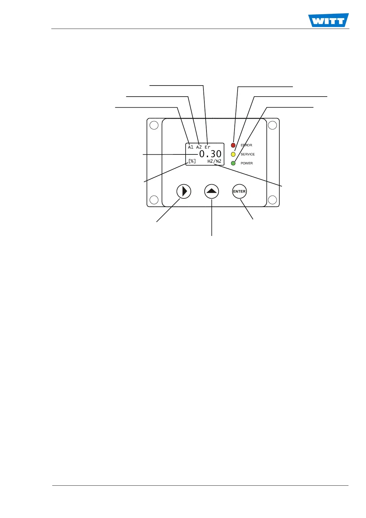
7.1 The Front Panel
7.1.1 Process Alarm and System Error Indicators
Process Alarm indicator 1 and 2 are directly connected to the Relays 1 and 2 settings, respectively.
The conditions for activation are explained in Section 7.5.2, “Relays Setup Menu”. The System Er-
ror Indicator is directly connected with the Common Relay described in Section 7.5.2.7. By default
this indicator is activated by system error described in Section 7.4.2, “Errors”.
7.1.2 System Alarm Indicator (red)
When this indicator flashes, it shows that a system and/or process error has occurred. In this case
the common alarm relay is activated as well. A detailed description of the errors leading to this indi-
cation is given in Section 7.5.2.7, “Common Relay”.
7.1.3 System Maintenance Indicator (yellow)
When this indicator flashes, it indicates that the instrument is still working but demands mainte-
nance.
7.1.4 Operation Indicator (green)
When this indicator flashes, it indicates that power is supplied and the internal processor works
properly.
Process Alarm 2 indicator
Process Alarm 1 indicator
System Maintenance indicator
gas concentration
[Vol%] or [ppm]
Toggle MGM Mode
Gas Selection in MGM-Mode