Page 40 of 46
WITT-GASETECHNIK GmbH & Co KG
Gas Safety- & Control Equipment
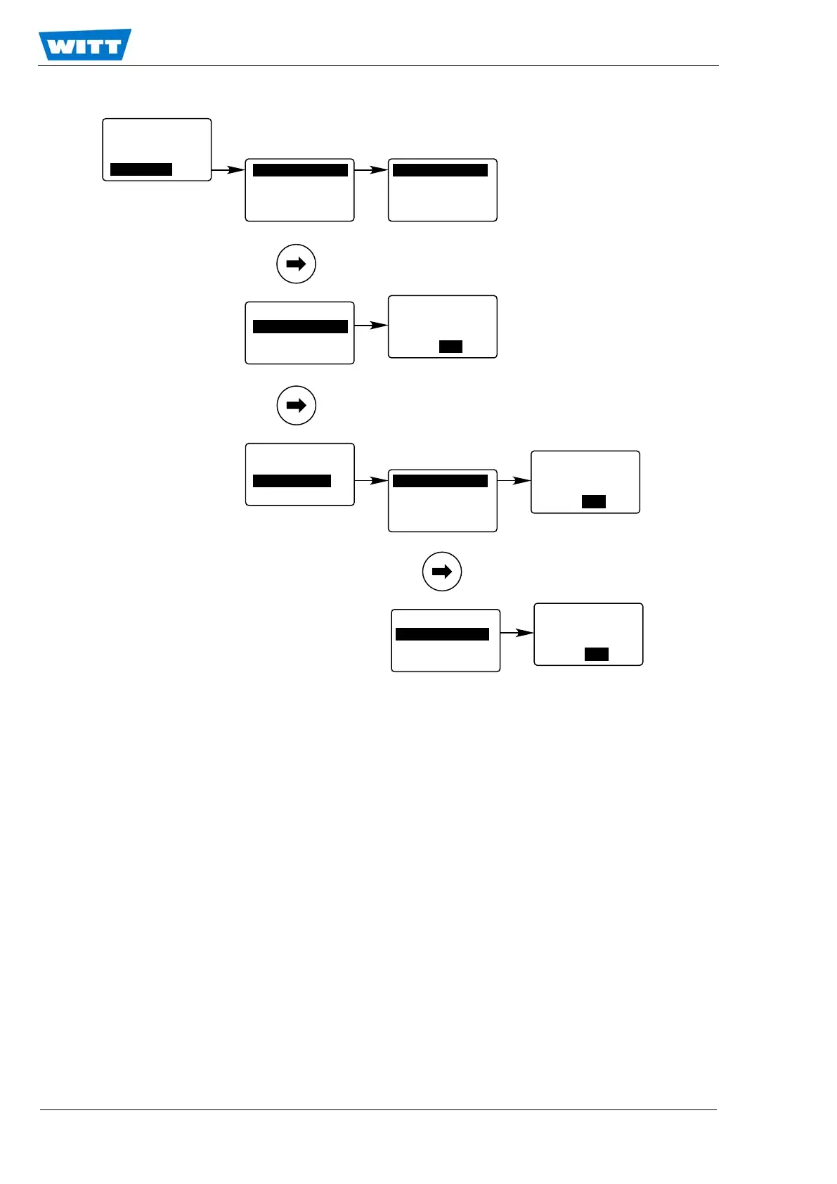
7.5.4.4 Test of Relays, Analog Outputs and Connections
The I/O Test menu gives the expert the possibility to test the relays, the analog outputs and the
subsequent connected equipment.
The alarm 1 relay (Rel 1), the alarm 2 relay (Rel 2) as well as the common alarm relay (Rel 3) may
be manually set to the desired status in order to test. The digital input “DIN” is monitored.
Appling 0V to the Digital Input will cause a low indication. +24V causes a high indication.
The output current loop can be set to feed a fixed current between 0 and 22 mA. The analog out-
puts 1 and 2 can be set to supply a fixed voltage between 0V and 10V.
Note!
All analog out test signals will be permanent until the I/O Test menu section is left. It is in
the responsibility of the expert to make sure that the I/O test does not irritate or harm the
subsequent connected systems and processes.
Parameter
Access Modes
Reset Funct.
I/O
Test
Relays
Current Loop
Analog Out
Rel 1 open
Rel 2 open
Re
l 3 open
DIN
low
Relays
C
urrent Loop
Analog Out
I-Out Const
set: 10.0000
new: 10.0000
[mA] ESC/OK
Relays
Current Loop
Analog Out An
alog Out 1
Analog O
ut
2
AO 1 Voltage
set: 0.00000
new: 0.00000
[V] ESC/OK
Analog Out 1
Anal
og Out 2
AO 2 Voltage
set: 0.00000
new: 0.00000
[V] ESC/OK