Page 9 of 46
WITT-GASETECHNIK GmbH & Co KG
Gas Safety- & Control Equipment
The calibration gases are supplied via the inlet port “Calibration gas” on the rear.
The respectively required calibration gases must be connected to this inlet port if a calibration is
executed. For valid inlet pressures see Technical Data.
Change over amongst the inlet ports occurs by means of the ball valve (47) at the front of the ana-
lyser.
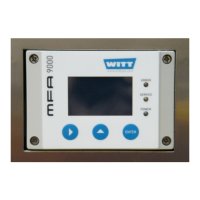
Via pressure regulator (49) the gas to be analysed is supplied to the analyser module (56). The gas
concentration is shown digitally in % or ppm on the display of the analyser.
The MFA also provides standardised output signals, 0-10 V and 4-20 mA corresponding to the
measured gas concentrations. The respective electrical interface is located at connector X1.
The measured gas concentrations can also be recorded through the RS 232 C interface (connect-
or X2).
Option To achieve a faster reaction to fluctuating measuring gas concentrations in the analysis gas a
bypass can be installed after the pressure regulator ex factory. The bypass causes a higher flow
rate of the analysis gas which causes faster reaction.
A flow guard (58) is installed in the outlet of the analyser to continuously monitor the analysis gas
flow. In case that the flow fall short of a pre-defined threshold limit (e. g. due to a leak in the sample
gas supply line), an alarm will be triggered.
Option The alarm signals (e.g. min. / max. concentration alarm, analysis gas fow alarm) will be exported
through volt free contacts.
Note!
In order to supply sample gas to the analyser (e.g. from a WITT gas mixer or a gas mixture
receiver) it is necessary to install a suitable gas line between the equipment where the gas
sample is taken from and the corresponding analysis gas inlet port of the gas analyser. The
installation of a suitable gas pipeline has to be performed by the customer. The gas inlet
pressures must be within the inlet pressure limits specified in the technical data section.
Proper pressure reducers should be installed in the gas supply lines to the analyser, if nec-
essary.
Note!
The analyser needs to be calibrated during initial start-up and on a regular schedule during
operation. To calibrate the gas analyser, proper calibration gases for calibration point 1 and
calibration point 2 must be supplied to the analyser.
Note!
Provisioning of proper calibration gas cylinders (see Technical Data), and installation of the
cylinders to the gas analyser are a customer responsibility. The calibration gas inlet con-
nector is located on the rear of the analyser (labeled “calibration gas”). The pressure cylin-
ders must be equipped with proper cylinder pressure reducers. The calibration gas inlet
pressure must not fall short of the minimum inlet pressure and must not exceed the maxi-
mum inlet pressure specified in the Technical Data.
All built-in pressure regulators are factory-set to the delivery status.
4.2.1 Technical data of the analyser
The technical data of the gas analyser are specified in the attached Technical Data sheets (please
refer to section 9).