2-11
Installation Information CT Hoods and DD Ventilation
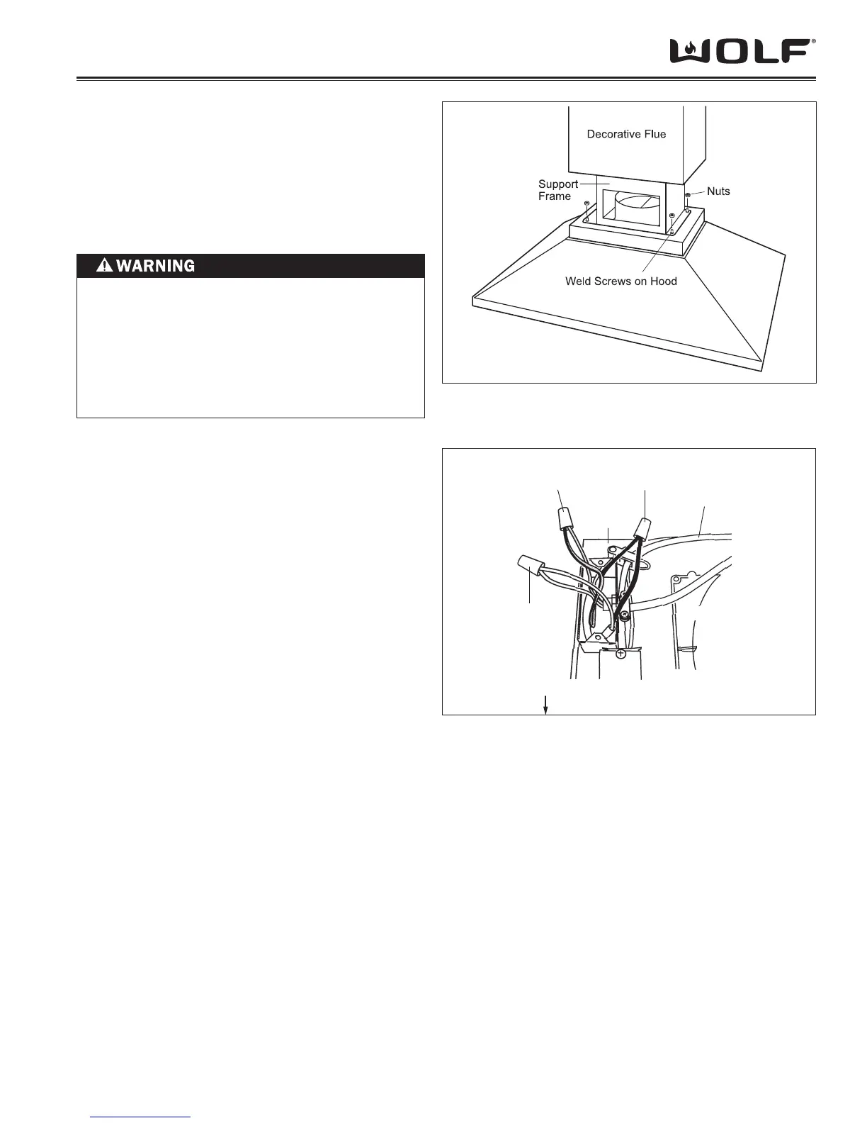
MOUNT HOOD TO SUPPORT FRAME
Temporarily secure the lower telescopic chimney 1.
fl ue section over the upper fl ue section.
Mount the hood to the support frame by aligning 2.
the four weld screws on the hood to the four holes
on the support frame. Use four nuts to secure the
hood to the support frame. (See Figure 2-19).
E
LECTRICAL CONNECTIONS
Remove the cover from the rear electrical box 1.
knockout that faces the hood’s discharge collar.
Insert 6” (152) of 120 VAC power cable through 2.
the knockout opening. Secure the cable to the
electrical box with an appropriate connector.
Make electrical connections. Connect black to 3.
black, white to white and green/yellow to green or
bare wire. (See Figure 2-20)
Reinstall the electrical box cover and screws. Make 4.
sure that all wires are secure and that no wires are
pinched between the cover and box.
Use an 8” (203) round metal duct to connect the 5.
duct collar on the hood to the ductwork above. Use
duct tape to make all joints secure and air tight.
Slide the lower telescopic chimney fl ue section 6.
downward until it fi ts properly around the hood
shell.
Green/Yellow to
Green or
Bare Wire
Black to
Black
HOOD FRONT TOP OF HOOD SHELL
Discharge
Collar
120 V AC
Power Cable
Rear
Electrical
Box
White
to White
TO REDUCE THE RISK OF ELECTRICAL SHOCK,
THIS VENTILATION HOOD MUST BE PROPERLY
GROUNDED.
UNIT SHOULD BE CONNECTED ELECTRICALLY
BY A QUALIFIED ELECTRICIAN IN ACCORDANCE
WITH ALL APPLICABLE NATIONAL AND LOCAL
ELECTRICAL CODES.
Figure 2-20 Electrical Connections
Figure 2-19 Mounting Hood to Support System