2-15
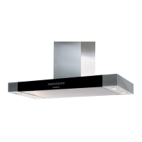
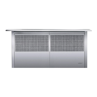
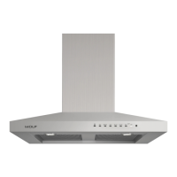
Installation Information CT Hoods and DD Ventilation
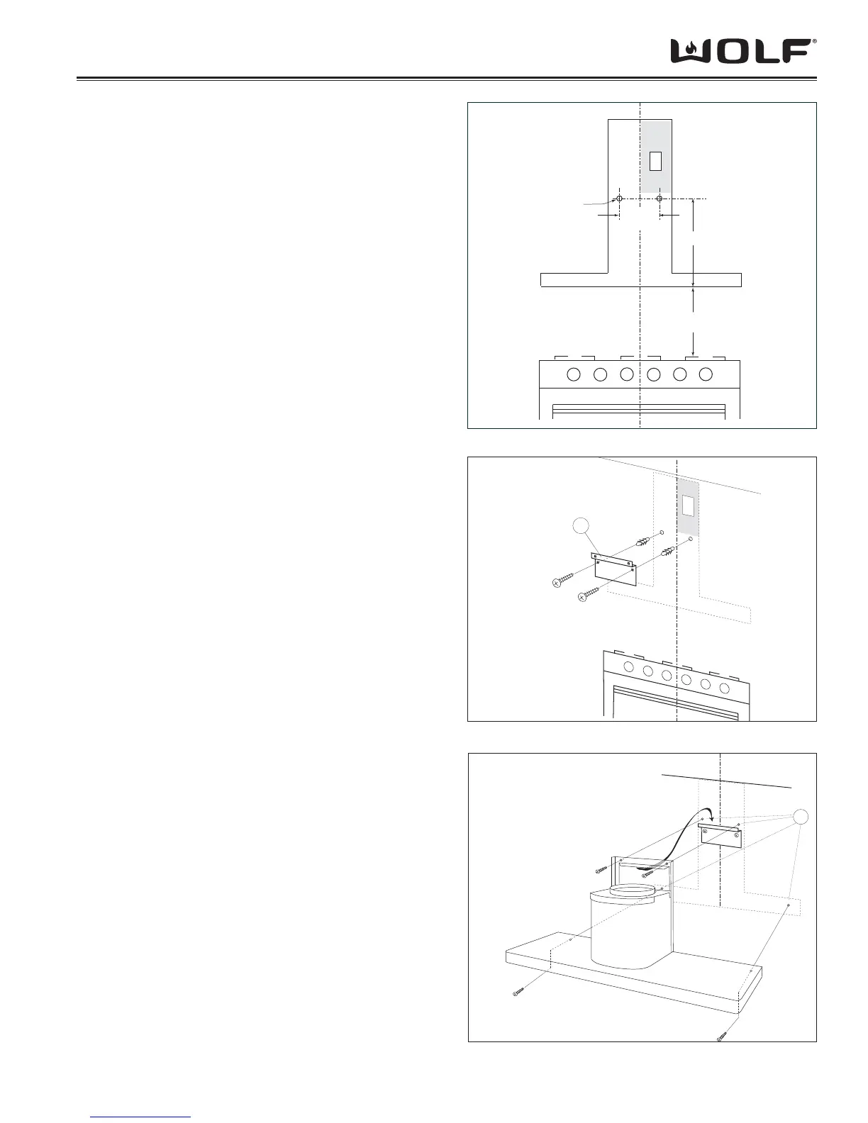
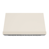
13 3/8” (340)
24" to 30" (610 – 762)
TO COOKING SURFACE
5 1/16”
(129)
5/16"
DIAMETER
E
4.8 x 38mm
A
E
4.8 x 38 mm
C
Figure 2-23 CTE Wall Hood Mounting Plate Placement
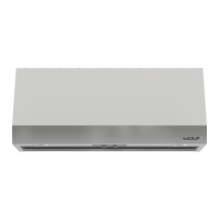
Figure 2-24 CTE Wall Hood Mounting Plate Mounting
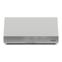
Figure 2-25 CTE Wall Hood Mounting
E
LECTRICAL REQUIREMENTS
Wolf low-profi le hoods require a separate, grounded,
110/120 VAC, 60 Hz power supply. The service should
have its own 15 amp circuit breaker.
NOTE: You must follow all National Electrical Code
regulations. In addition, be aware of local codes and
ordinances when installing your service.
F
IXING TO THE WALL
Draw a line on the wall in vertical line with your hood. 1.
Mark the fi rst two holes to be drilled in the wall, re-
specting the distances indicated in Figure 23. Drill the
two holes and fi t the screw anchors provided.
For best capture of cooking impurities, the bottom 2.
of the hood should be a minimum of 24” (610) and a
maximum of 30” (762) above THE COUNTERTOP.
Fix the metal bracket (A) to the wall using the two 3.
holes just drilled as shown in Figure 24. The screws
for fi xing the bracket are provided. Use the two cut-out
triangles on the bracket to position it exactly along the
vertical axis of the hood.
Hang the hood on the bracket as shown in Figure 4.
25. Adjust the horizontal position moving the hood
to the right or left so that it is aligned with the wall
units. When adjustment has been completed, without
removing the hood, mark the other four holes to be
drilled (C) in the wall. Remove the hood and drill the
holes marked (5/16” diameter). Then use the four
screw anchors and the four screws provided for fi nal
fi xing.
Mount the plate of the electrical system fi xing it with 5.
three screws.
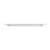
FIXING THE TELESCOPIC FLUE
Adjust the width of the support bracket (D) of the 1.
telescopic fl ue by means of the screws (E) as shown
in Figure 26. Then, by means of the screw anchors
and screws (F) provided, fi x the bracket to the ceiling
in such a way that it is positioned along the axis with
your hood.
Connect the air outlet pipe to the air vent of the hood. 2.
Use a fl exible pipe and lock it to the air vent of the
hood with a metal hose clamp as shown in Figure 27
(pipe and clamp are not provided).
For exhaust hoods, turn the upper fl ue over so that 3.
the air exhaust grid is in the lower section.