2-18
Installation InformationCT Hoods and DD Ventilation
ELECTRICAL REQUIREMENTS
Wolf low-profi le hoods require a separate, grounded,
110/120 VAC, 60 Hz power supply. The service should
have its own 15 amp circuit breaker.
NOTE: You must follow all National Electrical Code
regulations. In addition, be aware of local codes and
ordinances when installing your service.
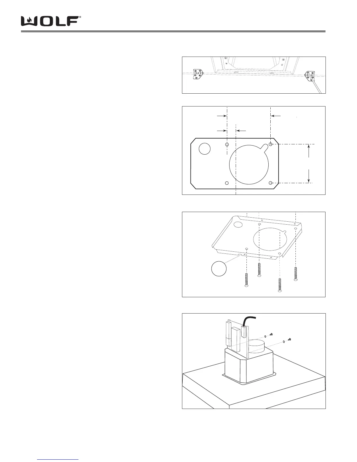
FIXING TO THE CEILING
Mount the metal panel with four screws as shown in 1.
Figure 31.
Using the drilling template, drill the holes for fi xing to 2.
the ceiling on the vertical side of your hood. The center
line of the mounting plate (Figure 32) is in line with
the center of the control panel. Carefully observe this
indication to ensure proper alignment of the hood with
the cooking product.
Fix the bracket to the ceiling using the screws and 3.
screw anchors provided as shown in Figure 33.
NOTE: The position of the bracket determines the fi nal
position of the hood. The side with the slot (B) corresponds
to the side opposite the controls.
Assemble the plate of the electrical system fi xing it with 4.
two screws and two metal washers as shown in Figure
34.
Fix the telescopic fl ue to the bracket by means of four 5.
screws (provided), running the air evacuation pipe
through the telescopic fl ue and the electric power cable
through the special hole in the bracket as shown in
Figure 35.
Adjust the height of the telescopic fl ue by means of the 6.
four retaining screws (C) shown in Figure 35. Take into
account that the height of the hood is 3 1/8” (79) and
the bottom of the hood should be a minimum of 24”
(610) and a maximum of 30” (762) above the counter-
top.
Take the upper fl ue (with the round slots) and slide it on 7.
the telescopic fl ue with the slots facing upwards. Attach
the fl ue to the bracket with two screws as shown in
Figure 36.
Take the lower fl ue and slide it over the upper fl ue, to 8.
the top and secure it in that position using adhesive
tape.
Raise the hood to the telescopic fl ue and connect 9.
the air outlet duct to the hood. Attach the hood to the
telescopic fl ue by means of four screws (provided) as
shown in Figure 37.
B
4.5 x 60mm
Figure 2-32 CTE Island Hood Plate Dimensions
5
15
/16” (151)
5
15
/16” (151)
1
3
/8” (35)
Figure 2-33 CTE Island Hood Ceiling Plate Mounting
Figure 2-31 CTE Island Hood Metal Panel Mounting
3.9 x 9.5mm
Figure 2-34 CTE Island Hood Control Plate
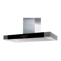
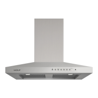
CTE ISLAND HOOD INSTALLATION