1-S29
L3130 · L3430 · L3830 · L4630 · L5030, WSM
ENGINE
Injection Pipes
1. Loosen the screws on the pipe clamps (1).
2. Detach the injection pipes (2).
(When reassembling)
• Blow out dust inside the pipes.
W1060970
Nozzle Holder Assembly and Glow Plug
1. Remove the overflow pipe assembly (5).
2. Remove the nozzle holder assemblies (2) using a 21 mm deep
socket wrench.
3. Remove the copper gasket and heat seal (3).
4. Remove the glow plugs (1).
(When reassembling)
• Replace the copper gasket and heat seal with new one.
W1020917
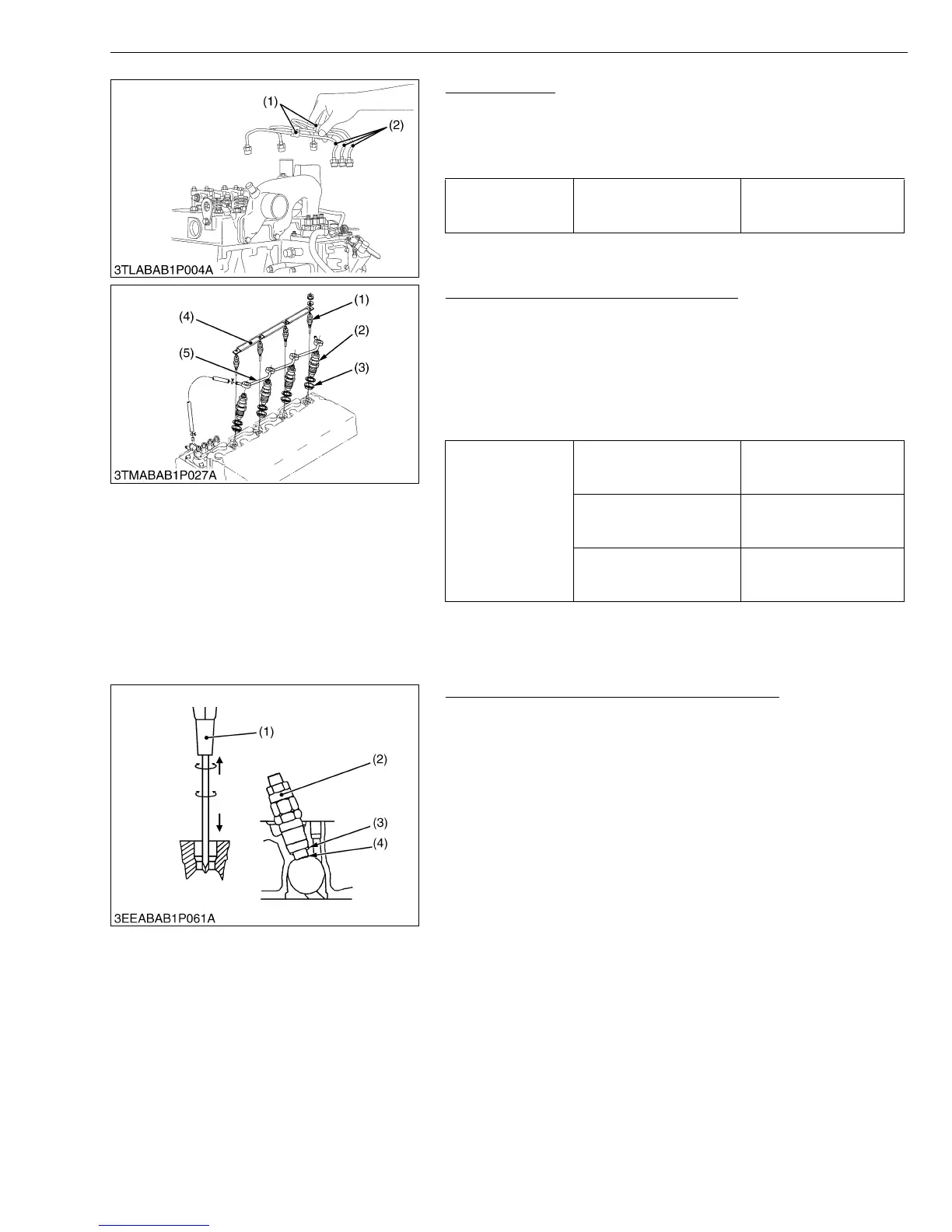
Nozzle Heat Seal Service Removal Procedure
• Use a plus (phillips head) screw driver (1) that has a Dia.
which is bigger than the heat seal hole (Approx. 6 mm) 1/4 in.
1. Drove screw drive (1) lightly into the heat seal hole.
2. Turn screw driver three or four times each way.
3. While turning the screw driver, slowly pull the heat seal (4) out
together with the copper gasket (3).
4. If the heat seal drops, repeat the above procedure.
(When reassembling)
• Heat seal and copper gasket must be changed when the injection
nozzle is removed for cleaning or for service.
W1021255
Tightening torque Injection pipe retaining nut
24.5 to 34.3 N·m
2.5 to 3.5 kgf·m
18.1 to 25.3 ft-lbs
(1) Pipe Clamp (2) Injection Pipe
Tightening torque
Nozzle holder assembly
49.0 to 68.6 N·m
5.0 to 7.0 kgf·m
36.2 to 50.6 ft-lbs
Overflow pipe assembly
retaining nut
19.6 to 24.5 N·m
2.0 to 2.5 kgf·m
14.5 to 18.1 ft-lbs
Glow plug
19.6 to 24.5 N·m
2.0 to 2.5 kgf·m
14.5 to 18.1 ft-lbs
(1) Glow Plug
(2) Nozzle Holder Assembly
(3) Heat Seal
(4) Lead
(5) Overflow Pipe Assembly
(1) Plus Screw Driver
(2) Nozzle Holder
(3) Copper Gasket
(4) Heat Seal