8-S9
L3130 · L3430 · L3830 · L4630 · L5030, WSM
HYDRAULIC SYSTEM
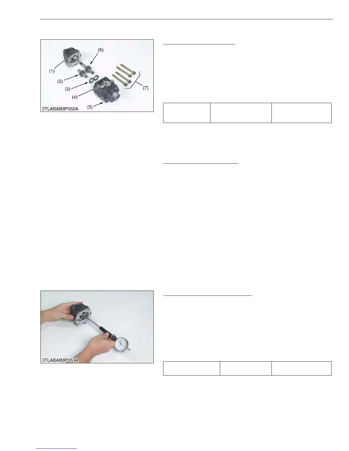
(B) Disassembling Hydraulic Pump
Hydraulic Pump Assembly
1. Remove the pump cover mounting screws (7).
2. Remove the drive gear (6), driven gear (2) and side plate (3) from
the casing.
(When reassembling)
• Take care not to damage the gasket.
• Align the hole of the pump cover (5) and casing 2 (4).
• Install the side plate, noting its location and direction.
• Install the gears, noting its direction.
W10135590
Hydraulic Pump Running-In
After reassembly, perform break-in operation in the following
manner, and check the pump for abnormality before use. If the
pump temperature should rise noticeably during running-in, recheck
should be performed.
1. Install the hydraulic pump to the tractor, and mount the suction
pipe and delivery pipe securely.
2. Set the engine speed at 1300 to 1500 min
−1
(rpm), and operate
the hydraulic pump at no load for about 10 minutes.
3. Set the engine speed at 2000 to 2200 min
−1
(rpm), and with the
hydraulic pump applied with 2.94 MPa (30 kgf/cm
2
, 427 psi) to
4.90 MPa (50 kgf/cm
2
, 711 psi) pressure, operate it for approx.
15 minutes.
4. With the engine set to maximum speed, fully turn the steering
wheel to the left or right, then actuate the relief valve five times
for 25 seconds (one time 5 seconds).
W10145360
(3) Servicing
Housing Bore (Depth of Scratch)
1. Check for the scratch on the interior surface of the housing
caused by the gear.
2. If the scratch reaches more than half the area of the interior
surface of the housing, replace at pump assembly.
3. Measure the housing I.D. where the interior surface is not
scratched, and measure the housing I.D. where the interior
surface is scratched.
4. If the values obtained in the two determinations differ by more
than the allowable limit, replace the hydraulic pump as a unit.
(Reference)
• Use a cylinder gauge to measure the housing I.D.
W10146490
Tightening torque
Pump cover mounting
screw
39.2 to 44.1 N·m
4.0 to 4.5 kgf·m
28.9 to 32.5 ft-lbs
(1) Casing 1
(2) Driven Gear
(3) Side Plate
(4) Casing 2
(5) Pump Cover
(6) Drive Gear
(7) Screw
Depth of scratch Allowable limit
0.09 mm
0.0035 in.