10-M6
L3130 · L3430 · L3830 · L4630 · L5030, WSM
CABIN
[3] ELECTRICAL SYSTEM
(1) Electrical Circuit
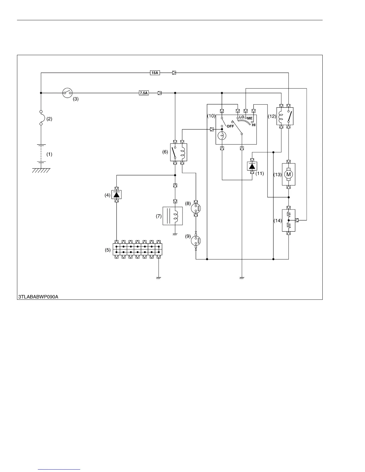
The process of magnetic clutch being engaged is shown below.
Main Switch (3) ON → A/C Switch (10) ON → Blower Switch (10) ON (Low, medium or High) → Compressor Relay
Contact (6) → Thermo Switch (7) ON (the thermostat temperature is more than 4 °C (39.2 °F)) → Pressure Switch (8)
ON (if refrigerant pressure is between 0.21 MPa (2.1 kgf/cm
2
, 30 psi) and 2.65 MPa (27 kgf/cm
2
, 384 psi) → Magnetic
Clutch of Compressor (7) Engaged.
(1) Battery
(2) Slow Blow Fuse
(3) Main Switch
(4) Diode
(5) Joint Connector
(6) Compressor Relay
(7) Compressor
(8) Pressure Switch
(9) Thermostat
(10) A/C Blower Switch
(11) Diode
(12) A/C Blower Relay
(13) A/C Blower Motor
(14) A/C Blower Resistor