8-M22
L3130 · L3430 · L3830 · L4630 · L5030, WSM
HYDRAULIC SYSTEM
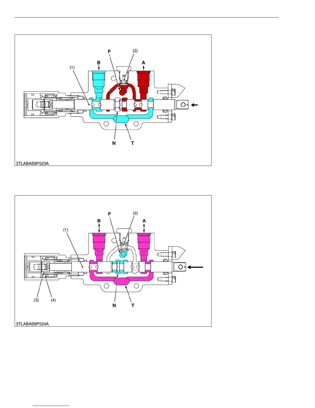
■ Down
W1016237
When the spool (1) is moved in the direction of the arrow, the pressure-fed oil in the P port opens the check valve
(2) and flows to the implement cylinder via A port.
Return oil from the implement cylinder flows from the B port to the transmission case through T port.
■ Floating
W1016319
When the spool (1) moves to extreme left, the detent ball (3) and detent sleeve (4) hold the spool (1) at the floating
position as shown in the figure. The pressure-fed oil from the hydraulic pump flows to position control valve via N port.
And, the A port and B port lead to the T port along the notched sections of the spool (1). This result in the attached
implement to follow the contour of the terrain.
(1) Spool
(2) Check Valve
A : A Port
(Implement Cylinder)
B : B Port
(Implement Cylinder)
P : Pump Port
N : Neutral Port
T : Tank Port
(1) Spool
(2) Check Valve
(3) Detent Ball
(4) Detent Sleeve
A : A Port
(Implement Cylinder)
B : B Port
(Implement Cylinder)
P : Pump Port
N : Neutral Port
T : Tank Port