9-M26
L3130 · L3430 · L3830 · L4630 · L5030, WSM
ELECTRICAL SYSTEM
(C) Testing, Setting and Adjusting Function
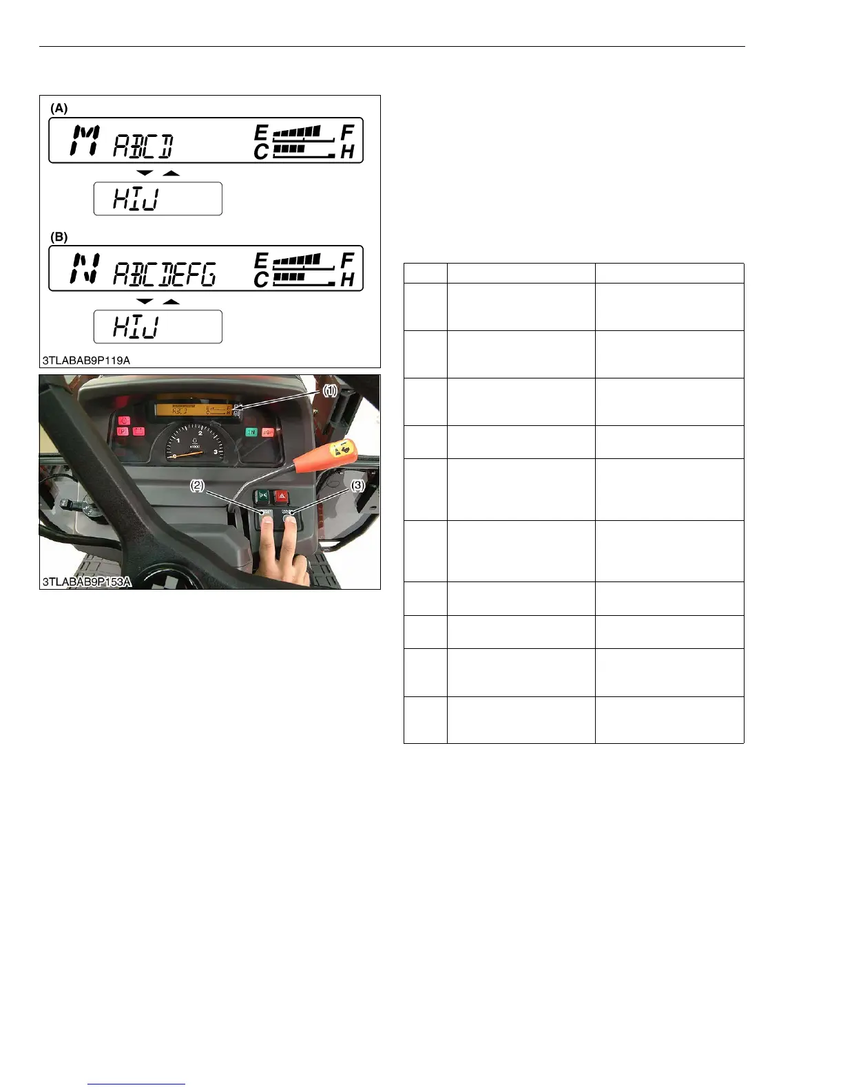
It can do various settings, adjustments and testing by
using the electronic instrument panel (IntelliPanel).
When the main switch is turned to ON or START
position while pushing both the display mode switch (2)
and the travel speed switch (3), the mode selection
display as shown in figure is indicated. And then, a target
mode is selected, the data input and the fine adjustment,
etc. can be done.
The following table shows the content of each mode
display by the alphabet.
W1019768
Sign Mode Name Contents
A Test Mode
For checking the sensors,
battery voltage and engine
revolution
B
Traveling Speed
Coefficient Input Mode
For inputting operation
coefficient of traveling
speed to IntelliPanel
C
PTO Coefficient Number
Input Mode
For inputting operation
coefficient number of PTO
to IntelliPanel
D
Error Information Reset
Mode
For deleting the error
information
E
GST Lever Sensor Fine-
adjustment Mode
For setting the Neutral
position of GST lever
sensor (Input the sensor
information to ECU)
F
GST Valve Fine-
adjustment Mode
For setting the function of
proportional reducing valve
(Input the valve
information to ECU)
G
GST Shift Shock Fine-
adjustment Mode
For adjusting the clutch
engaging interval
H
Error Information Display
Mode
For reviewing error
information (history)
I
Transmission Model Input
Mode
For inputting the
transmission model to
IntelliPanel
J Speed Unit Input Mode
For inputting the unit of
traveling speeds to
IntelliPanel
(1) LCD
(2) Display Mode Switch
(3) Travel Speed Switch
(A) Mode Selection Display for
HST and Manual
Transmission Model
(B) Mode Selection Display for
GST Model