EasyManua.ls Logo

Wunder-Bar JoeTap NITCOM - Page 47

Default Icon
95 pages
Print Icon
To Next Page IconTo Next Page
To Previous Page IconTo Previous Page
Loading...
Page | 47
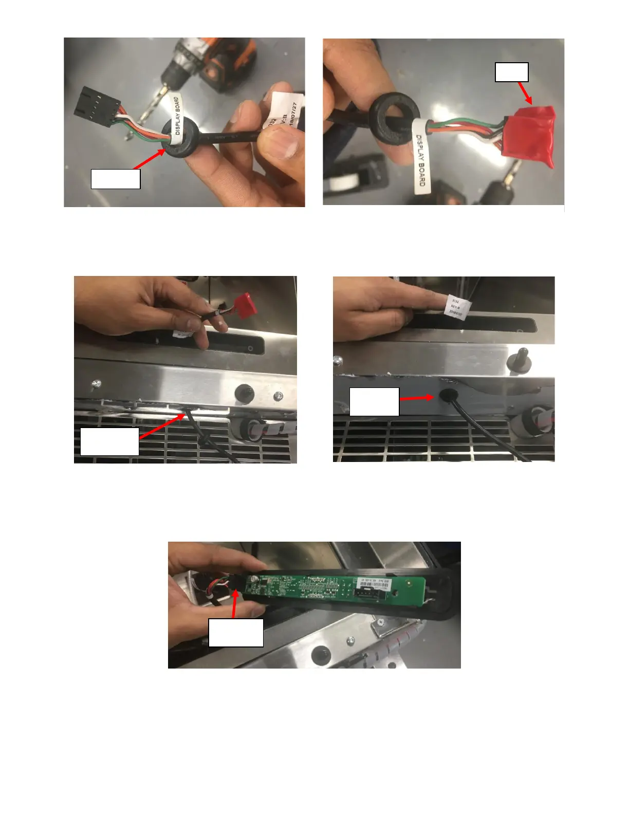
iii. Insert the Connector on the UI Harness through the bottom side of the Access Hole drilled in previous
step. See Figure 105a.
iv. Push the Grommet into the bottom side of the Access Hole to insert it. See Figure 105b.
f. Connect the UI Harness to the UI Board:
i. Remove the Electrical Tape over the Connector on the UI Harness and connect it to the UI Board. See
Figure 106.
ii. Pull the UI Harness into the UI Board Housing so that there is sufficient length in the housing. See
Figure 107.
Grommet
Tape
5/8” Access
Hole
Grommet
Installed
Harness
Connected
Figure 104a: UI Harness inserted into the Grommet.
Figure 104b: UI Harness connector covered with tape.
Figure 105a: UI Harness pushed through access hole.
Figure 105b: Grommet installed into access hole.
Figure 106: UI Harness connected to UI Board.

Table of Contents

Related product manuals