Page | 48
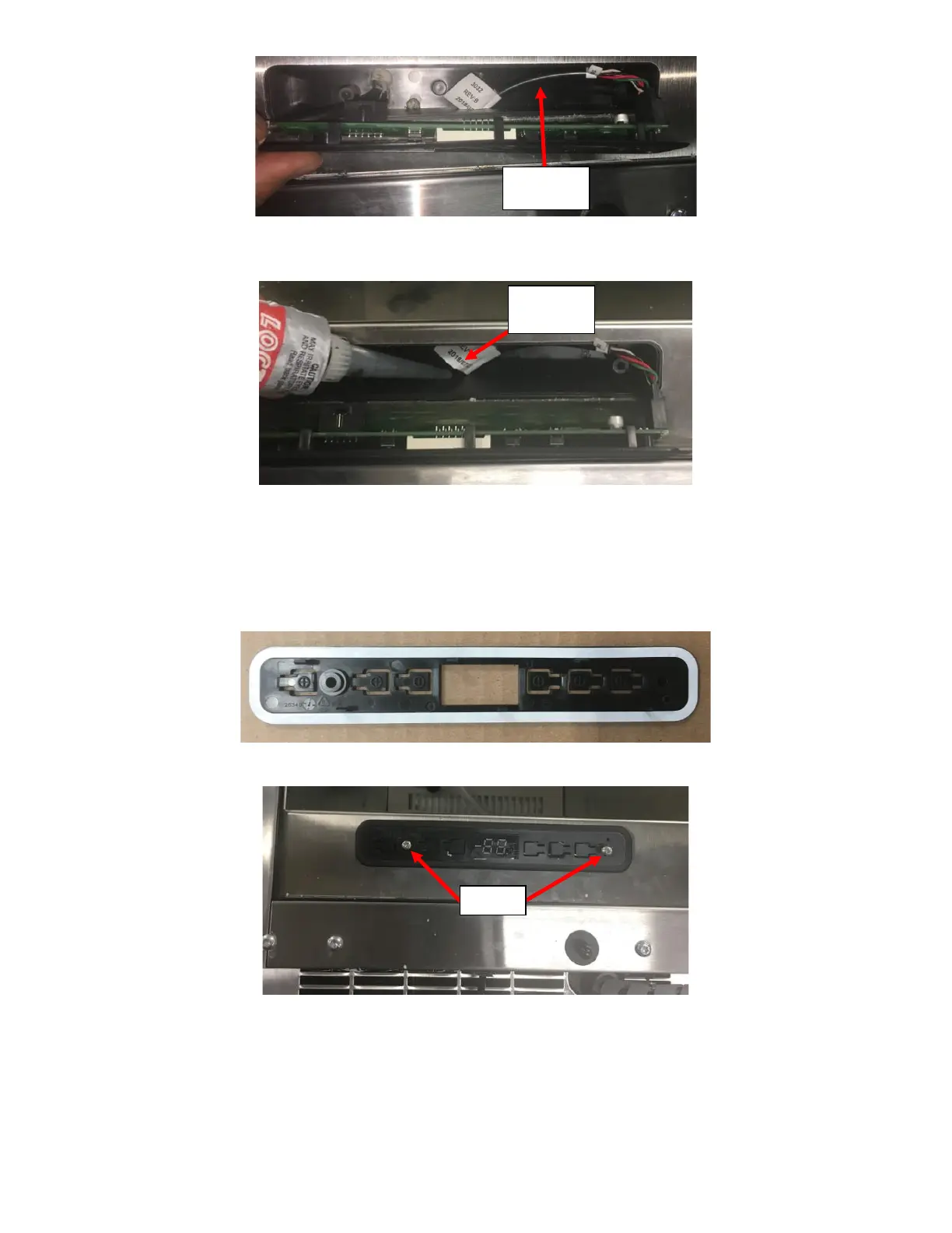
iii. Seal the Access Hole from inside the UI Housing with RTV. See Figure 108.
iv. Place LED UI Display/Board into the new Black Plastic Bracket.
v. Peel off the White Sticker on the new Black Plastic Bracket and place it into the UI Board Cavity. Ensure
the Fridge face is clean for proper adhesion. See Figure 109a.
vi. Reinstall the LED UI Display/Board and Black Plastic Bracket into the UI Board Cavity and secure it in
place with the two screws. See Figure 109b.
vii. Peel the sticker off the New Overlay and install the New Overlay. Do not reuse the Old Overlay. Make
sure to align the 7-segment LED. The light symbol should be on the right side. See Figure 97.