Page | 51
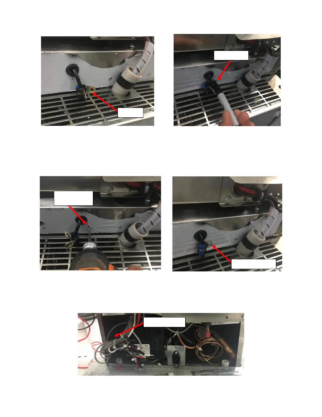
ii. Place the mounting surface of the P-Clamp flat onto the mounting surface of Fridge between the
Grommet and the Front Grill and mark the location of the Mounting Hole. See Figure 116a.
iii. Move the UI Harness and the P-Clamp out of the way and drill a pilot hole for the #10 Self-Drilling/Self-
Tapping Sheet Metal Screw provided with a #20 Drill Bit (Smaller Drill Bit is acceptable but do not use
an oversized Drill Bit). See Figure 117a.
iv. Align the Mounting Holes on the P-Clamp with the pilot hole and secure the P-Clamp with the #10
Sheet Metal Screw provided with a 5/16” Hex Drive Screwdriver. See Figure 117b.
i. Connect the UI Harness to the Control Board Harness:
i. Locate the existing UI Harness at the NITCOM Fridge Rear. It can be found in the bundle of wires next to
the inverter on the Left of the Fridge as seen from the rear of the Fridge. See Figure 118.