Page | 52
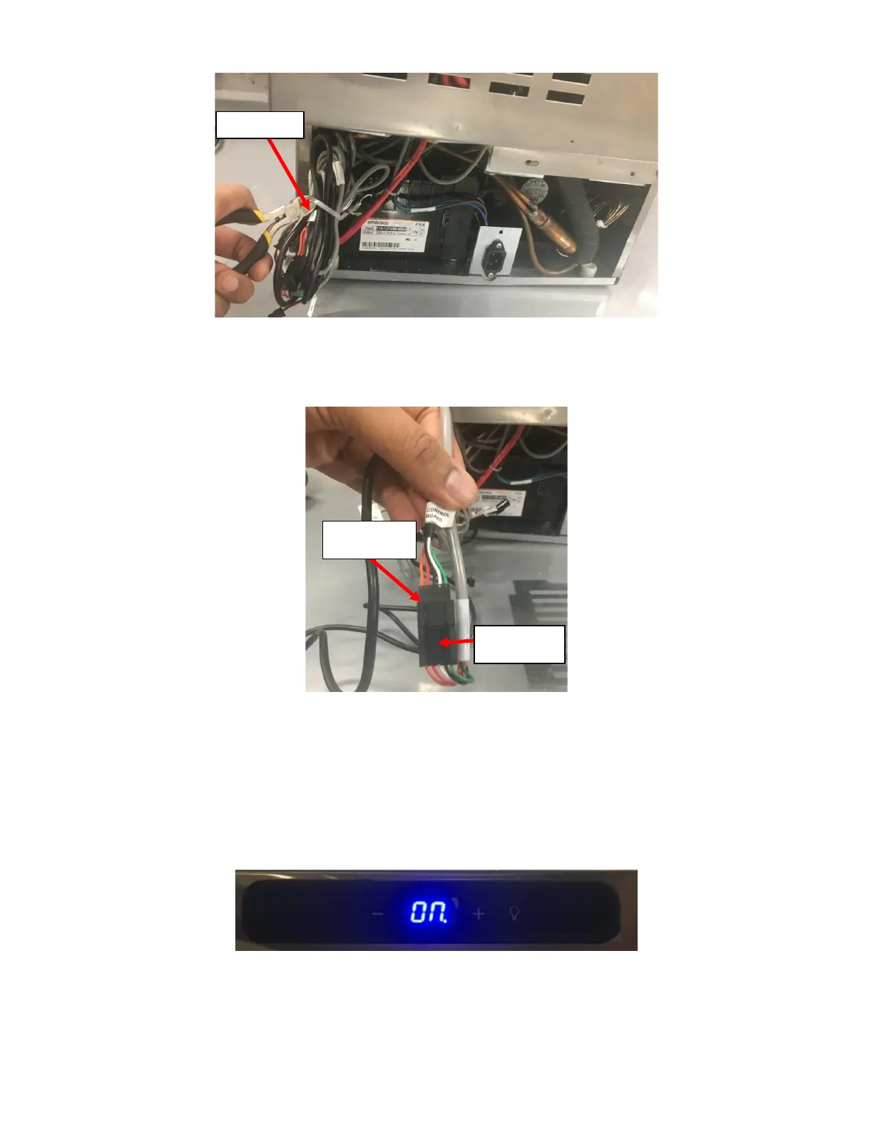
ii. Open the wire bundle by cutting the Cable Tie holding it together. See Figure 119.
iii. Disconnect the existing UI Harness once identified. The existing UI Harness should be identical to the
replacement UI Harness. The UI Harness should be connected to a Gray Harness leading to the Control
Board identified with a label J3(DISPLAY). See Figure 120.
iv. Connect the Connector on the replacement UI Harness to the Gray Harness labeled J3(DISPLAY) as
identified in the previous step.
j. Verify the repair worked and replace the Front Grill and Rear Grill:
i. Plug the NITCOM Fridge and verify that the UI Harness Replacement was done correctly. The Blue LED
on the Fridge Temperature Control should light up if it was done correctly. See Figure 121.
ii. Once the repair is verified, turn the NITCOM Fridge off.
iii. Find the existing UI Harness (the harness that is no longer used) and follow it up to where it is hidden
behind the Rear Enclosure on the Fridge. Cut the redundant/replaced UI Harness at this point. Be
careful to cut the correct wire and discard it. See Figure 122.