Page | 69
4.2. Insert the sub assembly into the tower:
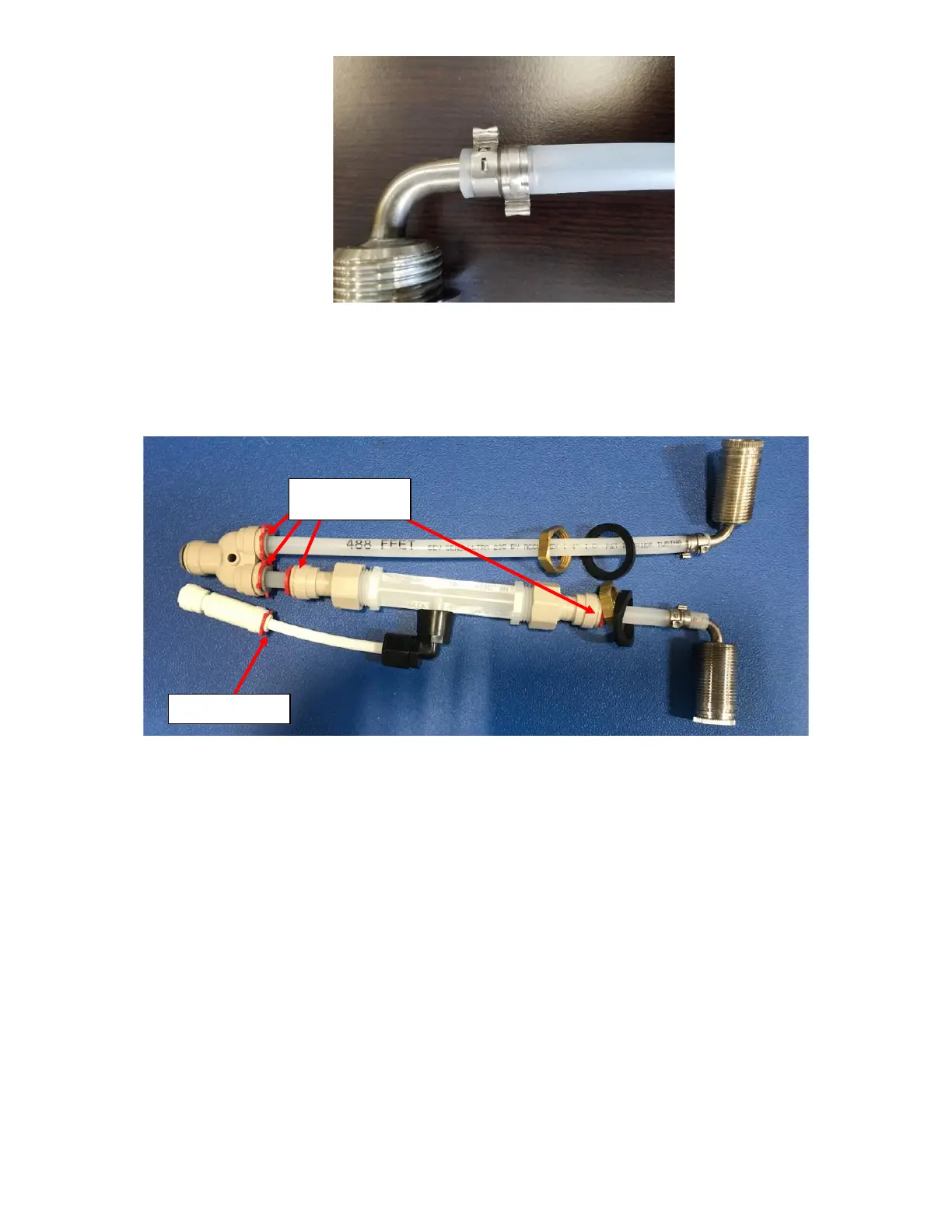
4.2.1. Check to verify all push to fit joints are secured with locking clips. There should be four (4) 3/8” Locking Clip
and one (1) ¼” Locking Clip for a total of five (5) locking clips. See Figure H18.
4.2.2. Place the tower upright and drop the sub assembly into the tower with the 2-Way Divider going in first. See
Figure H19.
4.2.3. Insert the Elbow Shank with the Venturi attached into the RIGHT tower hole when it is placed upright, and
the holes are facing towards you. See Figure H20.
4.2.4. Insert the Elbow Shank with the 10.5-inch Barrier Tubing inserted in the LEFT hole when it is placed upright,
and the holes are facing towards you. See Figure H21.