Page | 92
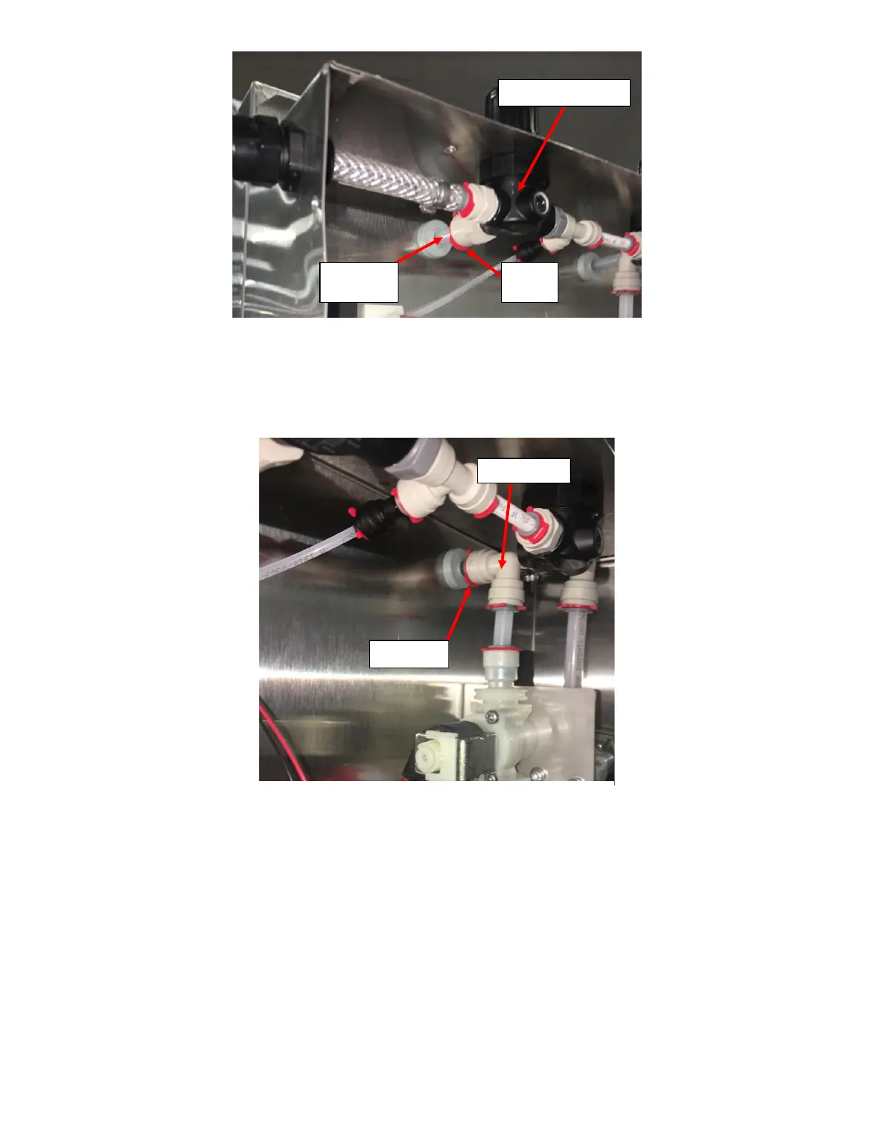
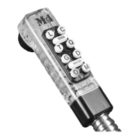
24. Turn the Solenoid Sub Assembly so that the Elbow attached to the subassembly is aligned with the Barrier Tubing
protruding from the Sealing Gray Grommet on the right and push the Elbow firmly to insert the tube into the Elbow
and install Locking Clip. See Figure L26.
25. Secure the Rear Enclosure in place by screwing in five Self Tapping #10-16 Screws with a 5/16” Hex Drive
Screwdriver through the TOP TWO SLOTs OUTSIDE THE REAR ENCLOSURE and all FOUR SLOTS INSIDE THE REAR
ENCLOSURE, See Figure 13 and Figure 14. Ensure that Blue Barrier Hose is not bent during the process. If the Blue
Barrier Hose is bent during the Rear Enclosure Installation process, remove the Rear Enclosure and the Blue Barrier
Hose. Discard the Blue Barrier Hose and replace the Barrier Hose with a new/unused hose. See Figure L27 and
Figure L28.
Figure L26: Elbow on Solenoid/Flowmeter Assembly inserted into
Barrier Tube on the Right of Enclosure with Locking Clip installed.