Basic Installation Procedures
975-0822-01-01 27
AC Output Connections
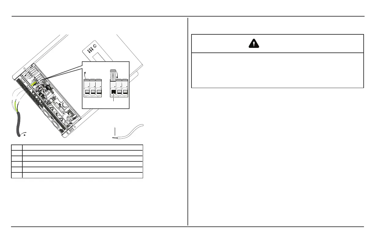
Figure 11 Routing and connecting the AC output wires
1 step 7a
2 step 7b
3 step 7c
4 15mm
5 to circuit breaker
NOTE: AC Output hole - install a bushing (supplied) or a strain-relief device.
To make a permanent connection to existing AC wiring:
1. Ensure AC and DC power sources are turned off, if not
already done from AC Output Connections on page 27.
2. Install the required circuit breaker in the inverter distribution
panel receiving AC power from the inverter.
3. Remove the wiring compartment cover, if not already done
from AC Output Connections on page 27.
WARNING
ELECTRIC SHOCK HAZARD
Use a screwdriver to loosen the captive nut panel screw.
Failure to follow these instructions can result in death, serious
injury, or equipment damage.
4. Strip a single AC output wire, as appropriate. Strip 10 mm off
the ends of each of the three the wires (tin the exposed
copper wire with lead-free solder using a soldering iron).
5. Remove the knockout and install 13mm strain relief clamp.
6. Route the wires through the strain relief clamp (not shown in
the figure
7.
Connect each AC wire into its corresponding terminal on the
no-tool cage clamp terminal block.
a. Lift the terminal lever (as shown on the figure).
b. Insert the wire fully into the open slot.
c. Lower the terminal lever to secure the wire in the slot.
8.
Make sure that each AC wire is matched and connected to
 Loading...