234 www.xilinx.com 7 Series FPGAs GTP Transceivers User Guide
UG482 (v1.9) December 19, 2016
Chapter 5: Board Design Guidelines
Crosstalk
A major contributor to degradation in the performance of an MGT is crosstalk. The mechanisms for
crosstalk are aggressor signals coupling into signal traces and/or coupling into the MGT power
supplies. The latter is the most common and often the most damaging. Noise coupled into the power
supply can corrupt the entire transceiver circuit rather than just a single lane as in the case of
coupling into signal traces. Also, the effect of noise coupled into the power supply is that the
symptoms are often more difficult to interpret because the noise is convolved with the normal
signals in the transceiver. The result is degradation in the performance of the transceiver that reveals
itself as noise in the transmitter output and reduced jitter tolerance in the receiver.
To avoid performance degradation from crosstalk:
• Monitor the exposure of power planes to other circuits on the board, such as data lines for
memory interfaces and processor busses.
• Provide adequate filtering to the MGT power supplies near the point of the load. The amount
of filtering should be determined by the magnitude and frequency of the signal from potential
noise sources. Noise on the MGT power supplies should be kept below 10 mV
PK-PK
from
10 kHz to 80 MHz.
• Be aware of the return current paths of signal traces in the vicinity of the MGT power
distribution network. Besides broadband and edge coupling of traces on the same or adjacent
layers, coupling from aggressor traces can occur if the aggressor signal is propagating from
one layer to another each layer having a different reference plane. As the signal propagates
through the portion of the via that does not have a return current path, it will generate return
currents in the next lowest impedance structure on the board. That victim could be a signal or
power via for the MGTs.
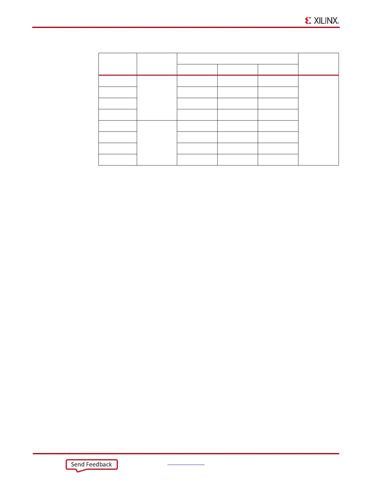
Table 5-13: FFG1156 Package – 0.1 µF Capacitor Placement
Capacitor
Power Supply
Group
Package Pins
Value
MGTAVCC MGTAVTT GND
Cap1
G10
AJ14 - AK14
0.1 µF
Cap2 AJ20 - AK20
Cap5 - AN14 AP14
Cap6 - AN22 AP22
Cap3
G11
F14 - E14
Cap4 F20 - E20
Cap7 - B14 A14
Cap8 - B22 A22