7 Series FPGAs GTP Transceivers User Guide www.xilinx.com 173
UG482 (v1.9) December 19, 2016
RX Buffer Bypass
Enabling and Disabling 8B/10B Decoding
To enable the 8B/10B decoder, RX8B10BEN must be driven High. RX_DATA_WIDTH must be set
to a multiple of 8 (8, 16, 32) when the 8B/10B decoder enabled.
To disable the 8B/10B decoder on the GTP transceiver receiver path, RX8B10BEN must be driven
Low. When the encoder is disabled, RX_DATA_WIDTH can be set to a multiple of 10 (10, 20, 40).
The operation of the RXDATA port with 8B/10B decoding bypassed is described in FPGA RX
Interface, page 214.
RX Buffer Bypass
Functional Description
Bypassing the RX elastic buffer is an advanced feature of the 7 series GTP transceiver. The RX
phase alignment circuit is used to adjust the phase difference between the PMA parallel clock
domain (XCLK) and the RXUSRCLK domain when the RX elastic buffer is bypassed. It also
performs the RX delay alignment by adjusting the RXUSRCLK to compensate for the temperature
and voltage variations. The combined RX phase and delay alignments can be automatically
performed by the GTP transceiver or manually controlled by the user. Figure 4-43 shows the XCLK
and RXUSRCLK domains, and Table 4-32 shows trade-offs between buffering and phase
alignment.
The RX elastic buffer can be bypassed to reduce latency when the RX recovered clock is used to
source RXUSRCLK and RXUSRCLK2. When the RX elastic buffer is bypassed, latency through
the RX datapath is low and deterministic, but clock correction and channel bonding are not
available.
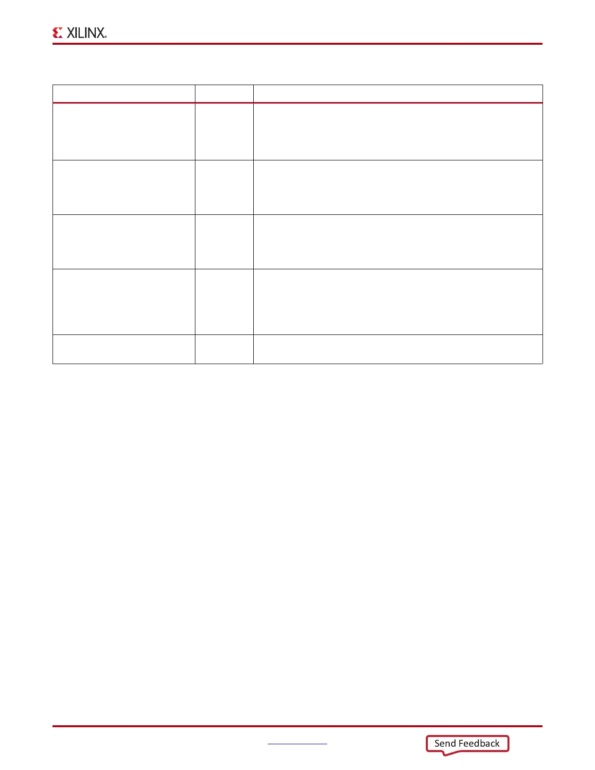
Table 4-28: RX 8B/10B Decoder Attributes
Attribute Type Description
RX_DISPERR_SEQ_MATCH StringString Specifies whether the disparity error status of a decoded byte must match the
indicator in the channel bonding and clock correction sequence.
When TRUE, indicates the disparity error status must be matched.
When FALSE, ignores the disparity error status.
DEC_MCOMMA_DETECT String When set to TRUE, drives the per byte flag RXCHARISCOMMA High
when an MCOMMA is detected.
When set to FALSE, RXCHARISCOMMA is Low when a negative comma
detected.
DEC_PCOMMA_DETECT String When set to TRUE, drives the per byte flag RXCHARISCOMMA High
when a PCOMMA is detected.
When set to FALSE, RXCHARISCOMMA is Low when a positive comma
detected.
DEC_VALID_COMMA_ONLY String When set to TRUE, drives the per byte flag RXCHARISCOMMA High
when only IEEE 802.3 valid commas K28.1, K28.5, and K28.7 are detected.
When set to FALSE, RXCHARISCOMMA is for positive or negative
8B/10B commas, depending how the user sets DEC_PCOMMA_DETECT
and DEC_MCOMMA_DETECT.
RX_DATA_WIDTH 3-bit Binary The PCS data width is set at the Fabric user interface with values of 16 or 32
(if 8B/10B decoding is not used) or 20 or 40 (if 8B/10B decoding is used).