174 www.xilinx.com 7 Series FPGAs GTP Transceivers User Guide
UG482 (v1.9) December 19, 2016
Chapter 4: Receiver
When RX buffer bypass is used, RXSLIDE_MODE cannot be set to AUTO or PMA.
Ports and Attributes
Table 4-29 defines the RX buffer bypass ports.
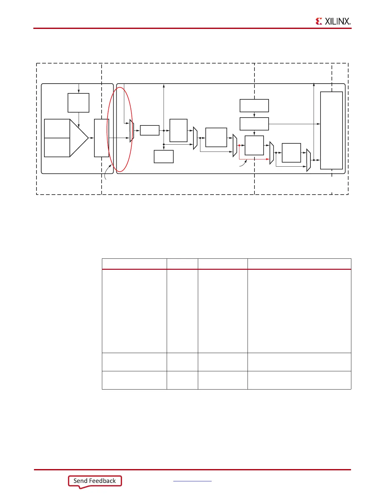
X-Ref Target - Figure 4-35
Figure 4-35: Using RX Phase Alignment
Clock from
PLL0 or PLL1
From TX Parallel
Data (Near-End
PCS Loopback)
To TX Parallel
Data (Far-End
PMA Loopback)
To TX Parallel
Data (Far-End PCS
Loopback)
FPGA Parallel
Clock
(RXUSRCLK2)
PCS Parallel
Clock
(RXUSRCLK)
PMA Parallel
Clock
(XCLK)
RX Serial
Clock
RX EQ
RX
Clock
Dividers
SIPO
RX OOB
Polarity
PRBS
Checker
Comma
Detect
and
Align
RX
Gear-
box
FPGA RX
Interface
8B/10B
Decoder
Bypass RX Elastic Buffer
After RX phase alignment:
- SPIO parallel clock phase matches RXUSRCLK phase.
- No phase difference between XCLK and RXUSRCLK.
RX
Elastic
Buffer
RX PIPE
Control
RX Status
Control
UG482_c4_24_111011
RX CDR
Table 4-29: RX Buffer Bypass Ports
Port Dir Clock Domain Description
RXPHDLYRESET In Async RX phase alignment hard reset to force
RXUSRCLK to the center of the delay
alignment tap. The delay alignment tap
has a full range of ±4 ns and a half range
of ±2 ns. This hard reset can be used to
initiate the GTP transceiver to perform
the RX phase and delay alignment
automatically when all other RX buffer
bypass input ports are set Low. It is
recommended to use RXDLYSRESET
only for phase and delay alignment.
RXPHALIGN In Async Sets the RX phase alignment. Tied Low
when using the auto alignment mode.
RXPHALIGNEN In Async RX phase alignment enable. Tied Low
when using the auto alignment mode.