64 www.xilinx.com 7 Series FPGAs GTP Transceivers User Guide
UG482 (v1.9) December 19, 2016
Chapter 2: Shared Features
TX and RX Power Down
When the TX and RX power control signals are used in non PCI Express implementations, TXPD
and RXPD can be used independently. Also, when these interfaces are used in non PCI Express
applications, only two power states are supported, as shown in Table 2-26. When using this
power-down mechanism, these must be true:
• TXPD[1] and TXPD[0] are connected together.
• RXPD[1] and RXPD[0] are connected together.
• TXDETECTRX must be strapped Low.
• TXELECIDLE must be strapped to TXPD[1] and TXPD[0].
Loopback
Functional Description
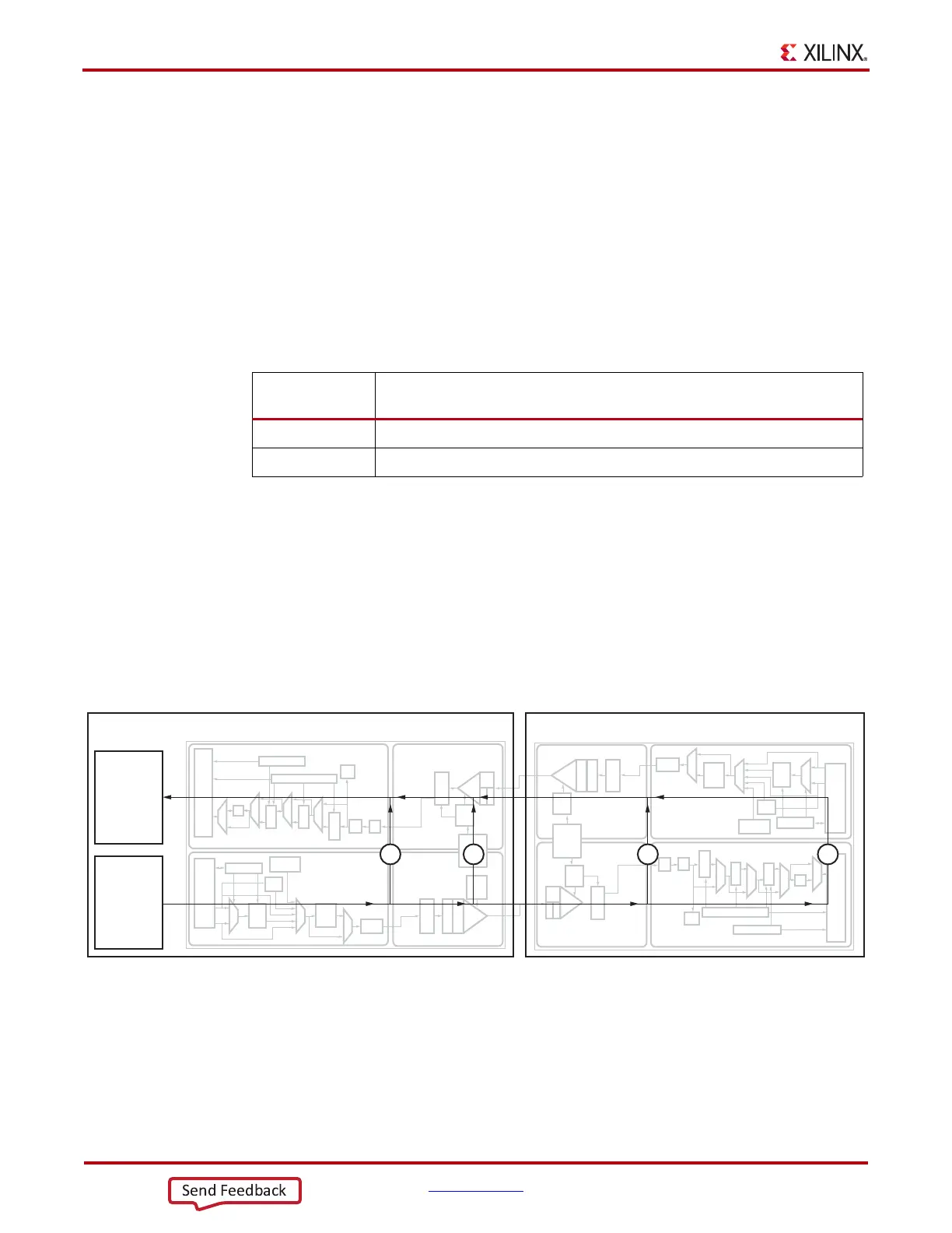
Loopback modes are specialized configurations of the transceiver datapath where the traffic stream
is folded back to the source. Typically, a specific traffic pattern is transmitted and then compared to
check for errors. Figure 2-22 illustrates a loopback test configuration with four different loopback
modes.
Loopback test modes fall into two broad categories:
• Near-end loopback modes loop transmit data back in the transceiver closest to the traffic
generator.
• Far-end loopback modes loop received data back in the transceiver at the far end of the link.
Table 2-26: TX and RX Power States for Operation that are not for PCI Express
Designs
TXPD[1:0] or
RXPD[1:0]
Description
00 Normal mode. Transceiver TX or RX is active sending or receiving data.
11 Power-down mode. Transceiver TX or RX is idle.
X-Ref Target - Figure 2-22
Figure 2-22: Loopback Testing Overview
Test Logic Near-End GTP
12 3 4
Far-End GTP
Link Near-End Test Structures Link Far-End Test Structures
Traffic
Checker
Traffic
Generator
RX-PCS
RX-PCS
TX-PCS
TX-PCS
TX-PMA
TX-PMA
RX-PMA
RX-PMA
UG482_c2_11_111111